Connecting
5.5 Sensor Installation
FUS1010 IP65 NEMA 4X & IP66 NEMA 7
Operating Instructions, 01/2013, A5E02951520-AC
65
4. Temporarily position one of the frames on the pipe where you will be mounting it. Ensure
that this is a smooth area without any raised areas (seams, etc.) With a pencil or chalk,
mark a generous area of 13 mm (1/2") all around the frame. Remove the assembly.
5. Prepare the area you marked by de-greasing surface, if needed, and removing any grit,
corrosion, rust, loose paint or surface irregularities with the abrasive material provided
6. Put a mounting strap around the pipe and engage an end into adjusting screw (screw
should be pointing up). Position frame in the middle of area you have cleaned and
centered on the pipe with its angled end facing away from where the other frame will sit.
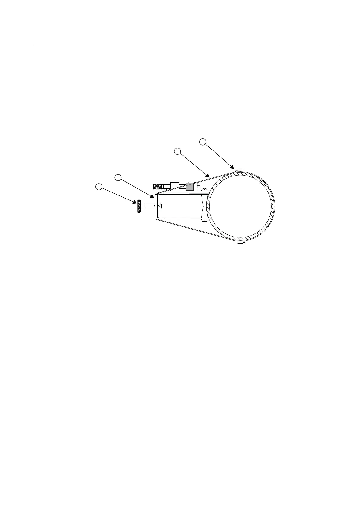
① ③ Sensor Clamping Screw Mounting Strap
② Spring Clip ④ Mounting Strap Adjusting Screw
Figure 5-16 Wrap Strap Under Pipe and Attach to Adjusting Screw
7. Slide the mounting strap over it (and under the clip if there is one) and tighten with a
screwdriver. While tightening, check to ensure that the center of the tapered roller is
centered on the pipe.
8. Attach the second frame to the spacer bar with an index spacer screw into the index hole
specified in Step 1. The angle on the frame should be facing away from the direction that
the length of the bar is going.