Connecting
5.5 Sensor Installation
FUS1010 IP65 NEMA 4X & IP66 NEMA 7
66 Operating Instructions, 01/2013, A5E02951520-AC
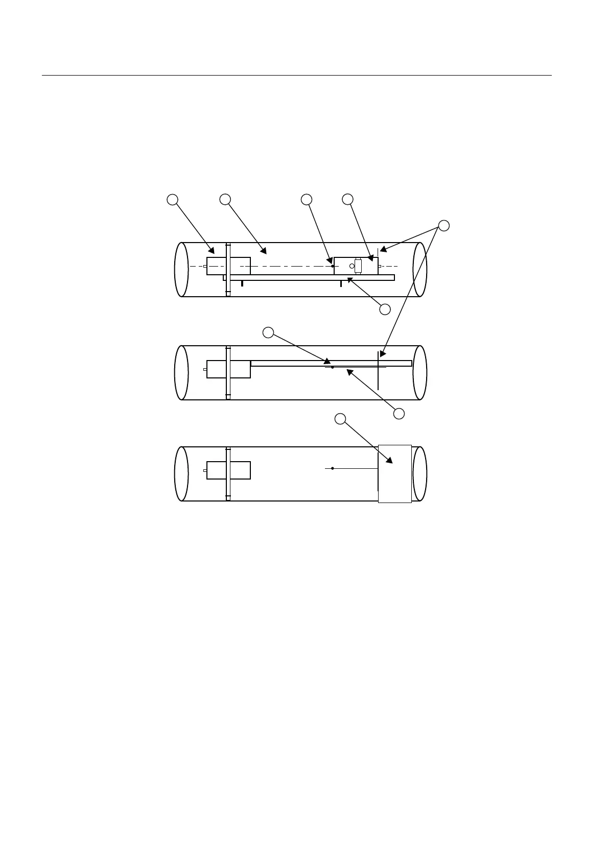
9. Now attach the free end of the spacer bar by inserting an index spacer screw through the
REF hole on the spacer bar and then into the hole on the mounted frame. Tighten. Sight
to ensure that this frame is lined up in center of pipe and while holding alignment, place a
dot (with pencil or chalk) in the center of the tapered roller at the bottom of the frame (see
A below). While holding, also mark along the front edge of the frame with pencil or fine
chalk line (see B below).
%
&
① ⑤ Sensor 1 Sensor Edge Line
② Pipe ⑥ Spacer Bar
③ Dot ⑦ Dot
④ Sensor 2 ⑧ Line
⑨ Mylar Spacing Guide