Connecting
5.5 Sensor Installation
FUS1010 IP65 NEMA 4X & IP66 NEMA 7
Operating Instructions, 01/2013, A5E02951520-AC
61
5.5.3 Reflect Mount
Reflect Mount - Sensor Installation using Mounting Frames and Spacer Bar
1. After receiving the spacing index from the Installation Menu, prepare the pipe surface
area where the sensors will be mounted.
2. Degrease the surface and remove any grit, corrosion, rust, loose paint, etc.
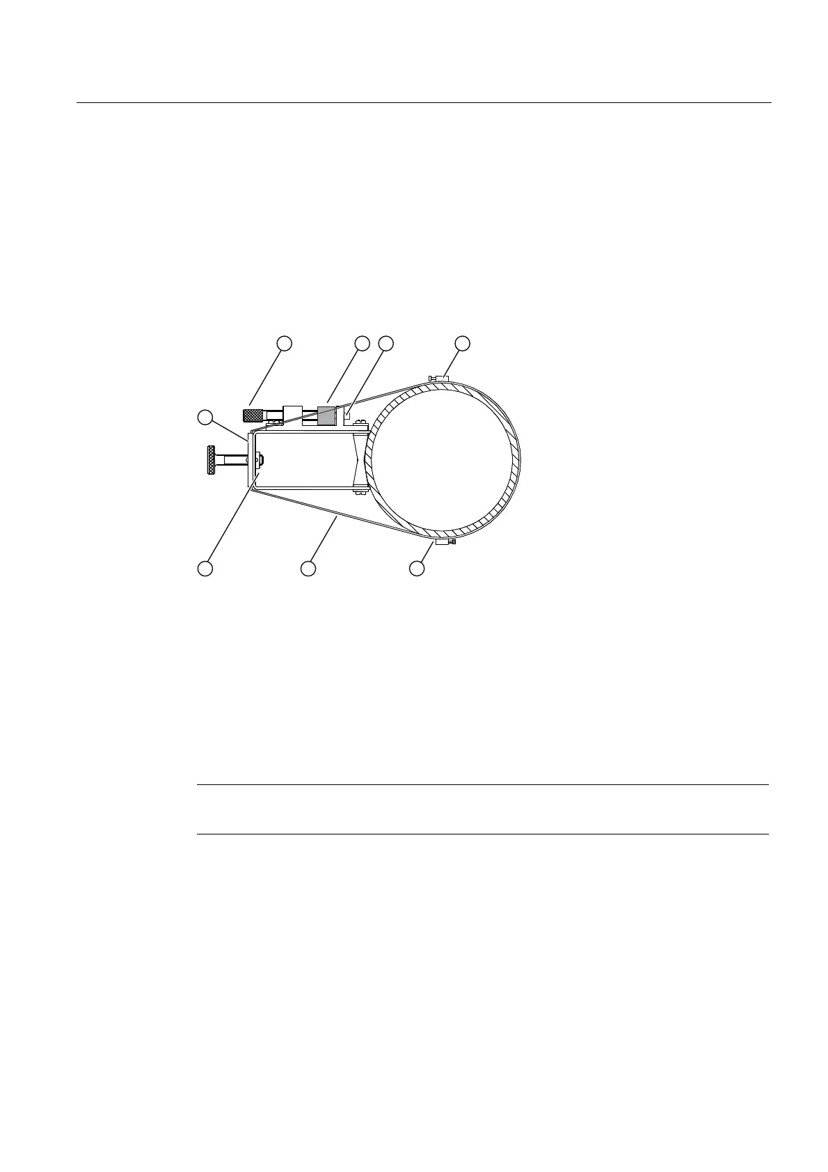
Before beginning refer to the Reflect Mount Installation diagram example below.
① Optional: On larger pipes, multiple lengths
of straps can be linked together to
surround pipe
⑤ Space Bar Platform & Clamping Screw
② Mounting Strap positioned around
Mounting Frame
⑥ Space Bar (Front View)
③ Sensor shown in the 9 o'clock position on
pipe
⑦ Metal Post
④ Mounting Frame ⑧ Mounting Strap Adjusting Screw
Figure 5-12 Reflect Mount with Mounting Frames and Spacer Bar
Note
Minimum Ltn
18 mm (0.75 in).
Ltn Menu Cell
This view only menu cell shows the distance in inches or millimeters between the front faces
of the sensors along the axis of the pipe. If you are mounting the sensors without a track or
spacer bar, you have to space them according to this value. Note that Ltn may be a negative
number for direct mount on very small pipes where the sensor spacing overlaps.

 Loading...


