Appendix
A.2 I/O Connections and Wiring
FUS1010 IP65 NEMA 4X & IP66 NEMA 7
Operating Instructions, 01/2013, A5E02951520-AC
189
Note
Relays shown in Power OFF position, which is the same as the alarm assertion position.
*7ME39400AL03 Mercury Relay only available with Normally Open.
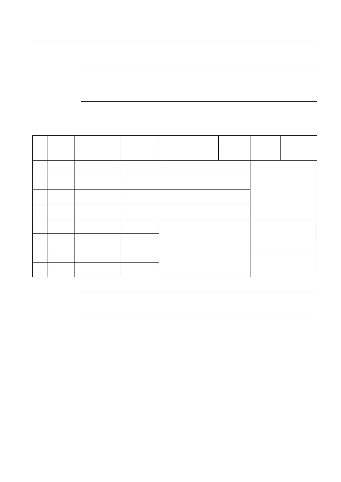
Table A- 7 Input/Output Wiring (TB4) - 7ME39400AL03 and 7ME39400AL04 Expanded I/O Module
Pin# Signal Definition Description Single CH
Function
Dual CH
Function
Dual Path
Function
Dual Path
Only
Function
Quad Path
Only
Function
1 AUX I01+ Isolated Loop
Supply Io1
Io1 External
Power
+30V max. supply voltage allowed
2 AUX I01- Io1 4-20mA
Output
Io1 Signal Same output assignment as TB2-9
3 AUX I02+ Isolated Loop
Supply Io2
Io2 External
Power
+30V max. supply voltage allowed
4 AUX I02- Io2 4-20mA
Output
Io2 Signal Same output assignment as TB2-11
Not Used
5 AUX I03+ Isolated Loop
Supply Io3
Io3 External
Power
6 AUX I03- Io3 4-20mA
Output
Io3 Signal
+30V max. Same as TB2-1
7 AUX I04+ Isolated Loop
Supply Io4
Io4 External
Power
8 AUX I04- Io4 4-20mA
Output
Io4 Signal
System outputs assignable and
scalable to flow related parameters.
4-20mA outputs also provide a fault
indication by dropping to 2mA if
assigned to flow rate and under fault
conditions.
+30V max. Same as TB2-3
Note
Auxiliary 4-20mA loops are assigned and spanned under menu control of Vo and PGEN
outputs.