Appendix
A.2 I/O Connections and Wiring
FUS1010 IP65 NEMA 4X & IP66 NEMA 7
192 Operating Instructions, 01/2013, A5E02951520-AC
Table A- 9 Input/Output Wiring (TB2) - 7ME39400AL04 Expanded I/O Module
Pin# Signal Definition Description Function
Dual/Quad Path Only
14 Chassis Ground Chassis Ground Cable Shield Terminations
13 Chassis Ground Chassis Ground Cable Shield Terminations
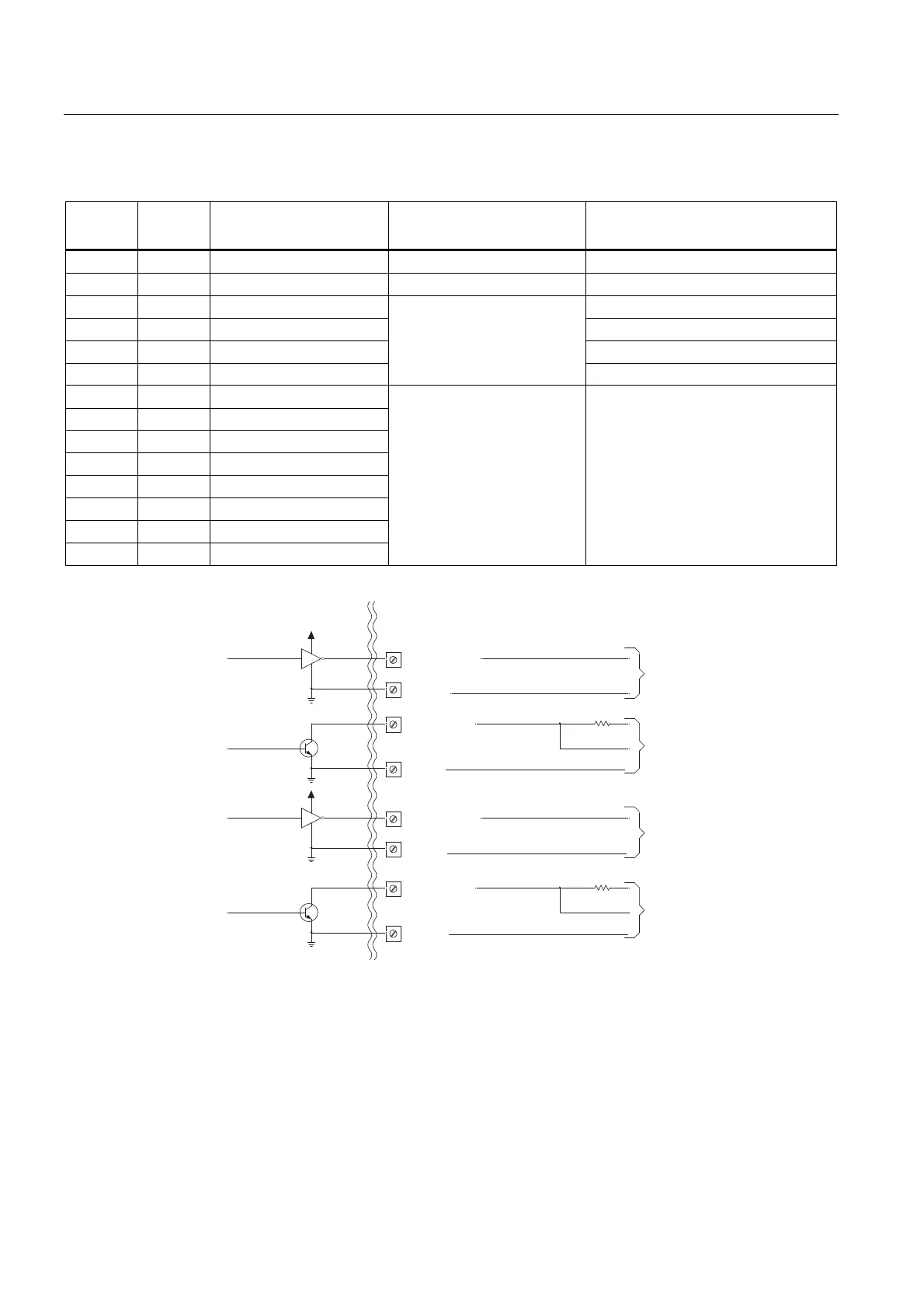
12 PG4 POS [+] Total TTL POS [+] Total TTL
11 PG3 POS [+] Total OC POS [+] Total OC
10 PG2 NEG [-] Total TTL NEG [-] Total TTL
9 PG1 NEG [-] Total OC
Totalizer Pulses, scalable
NEG [-] Total OC
8 Io2 (-) Isolated Return
7 Io2 (+) 4-20mA Output 2
6 Io1 (-) Isolated Return
5 Io1 (+) 4-20mA Output 1
4 Vo2- Ref. Ground
3 Vo2+ 0-10 Volt Output
2 Vo1- Ref. Ground
1 Vo1+ 0-10 Volt Output
Flow meter process variables
assigned to individual outputs
under menu control.
System outputs assignable & scalable
to flow related parameters.
4-20mA outputs also provide
a fault indication by dropping
to 2mA if assigned to flow
rate and under fault
conditions.
OC = Open Collector
+5V
+5V
PG1
PG3
PG4
1
32
1
32
PG2
DPGEN_1-Ø1
DPGEN_1-Ø2
DPGEN_2-Ø2
DPGEN_2-Ø1
2
3
4
5
TTL/CMOS
2
3
4
5
TTL/CMOS
0($/0($/
,2&211(&7,21%2$5'
0$,1%2$5'
7%'3*(1B
77//2*,&
5(9(56()/2:
7%*1'
>9R@
7%'3*(1B
23(1&2//(&725
5(9(56()/2:
7%*1'
>9R@
77/3*(16,*1$/
*5281'
6((7$%/(
2&3*(16,*1$/
*5281'
72(1'86(5
(48,30(17
9'&P$
120,1$/&855(17
&2168037,21
72(1'86(5
(48,30(17
7%'3*(1B
77//2*,&
)25:$5')/2:
7%*1'
>9R@
7%'3*(1B
23(1&2//(&725
)25:$5')/2:
7%*1'
>9R@
77/3*(16,*1$/
*5281'
6((7$%/(
2&3*(16,*1$/
*5281'
72(1'86(5
(48,30(17
9'&P$
120,1$/&855(17
&2168037,21
72(1'86(5
(48,30(17