Connecting
5.7 Sensor Wiring
FUS1010 IP65 NEMA 4X & IP66 NEMA 7
80 Operating Instructions, 01/2013, A5E02951520-AC
Clamp-on Sensors
Clamp-on style sensors are mounted on the surface of the monitored pipe using series
mounting assemblies. Apply a generous quantity of the thermal couplant provided to the tip
of the sensor and attach it securely to the cleaned pipe surface with the proper mounting
assembly. Temperature measurement anomalies resulting from variations in the ambient
conditions can be minimized by insulating the pipe and sensor after installation.
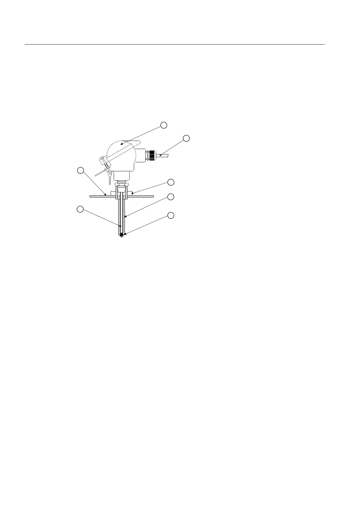
① Temperature Sensor Connector Head
Assembly
⑤ Thermal Couplant
② 7ME39600CR 992EC Series Cable ⑥ Spring Loaded Sensing Element
③ Threaded Pipe Fitting ⑦ Pipe Wall
④ Thermowell
Figure 5-27 Insert Temperature Sensor
Insert sensors are designed to be used in pipes equipped with Thermowells. These are
spring-loaded, 1/4" diameter sensors with 1/2" NPT integral connection heads, available in
several lengths to accommodate a range of pipe sizes.
Proceed to Commissioning (Page 83).
5.7 Sensor Wiring
Connecting Sensors to the Transmitter
1. Open the transmitter top cover. Using a flat blade screwdriver, remove the Cable Strain
Relief bracket (see figure below).
2. Observing the upstream and downstream orientation, attach the UP (upstream) and DN
(downstream) cables to the sensors and make snug. Attach the other ends to the UP and
DN terminals of the flow meter (see figure below).
3. Replace the Cable Strain Relief bracket. Close top cover.