Connecting
5.5 Sensor Installation
FUS1010 IP65 NEMA 4X & IP66 NEMA 7
64 Operating Instructions, 01/2013, A5E02951520-AC
2. Slide sensor into a mounting frame back end first aligning the angled edge of the sensor
with the angled edge of the mounting frame. Keep sensor from making contact with the
pipe until it butts up against the mounting frame stop. Push sensor down to mate with
pipe.
3. Tighten the sensor clamping screws to hold the sensor firmly in place.
Repeat procedure
for the other sensor.
4. If installing a temperature sensor proceed to Mounting Temperature Sensor (Page 78). If
not, proceed t
o Sensor Wiring (Page 80).
5.5.4 Direct Mount
Sensor Installation using Mounting Frames, Spacer Bar and Spacing Guides
The combination of mounting frames, spacer bar and spacing guides is the recommended
way to mount Direct Mode sensors. The mounting frame establishes the axial alignment of
the sensors and allows you to remove and replace either sensor while preserving their exact
mounting location.
For Direct Mode mounting, a spacer bar is used to establish the distance between sensors
and a spacing guide to locate the sensors at the nine o’clock and three o’clock positions.
Should the distance between sensors be beyond the span of a spacer bar, a measuring tape
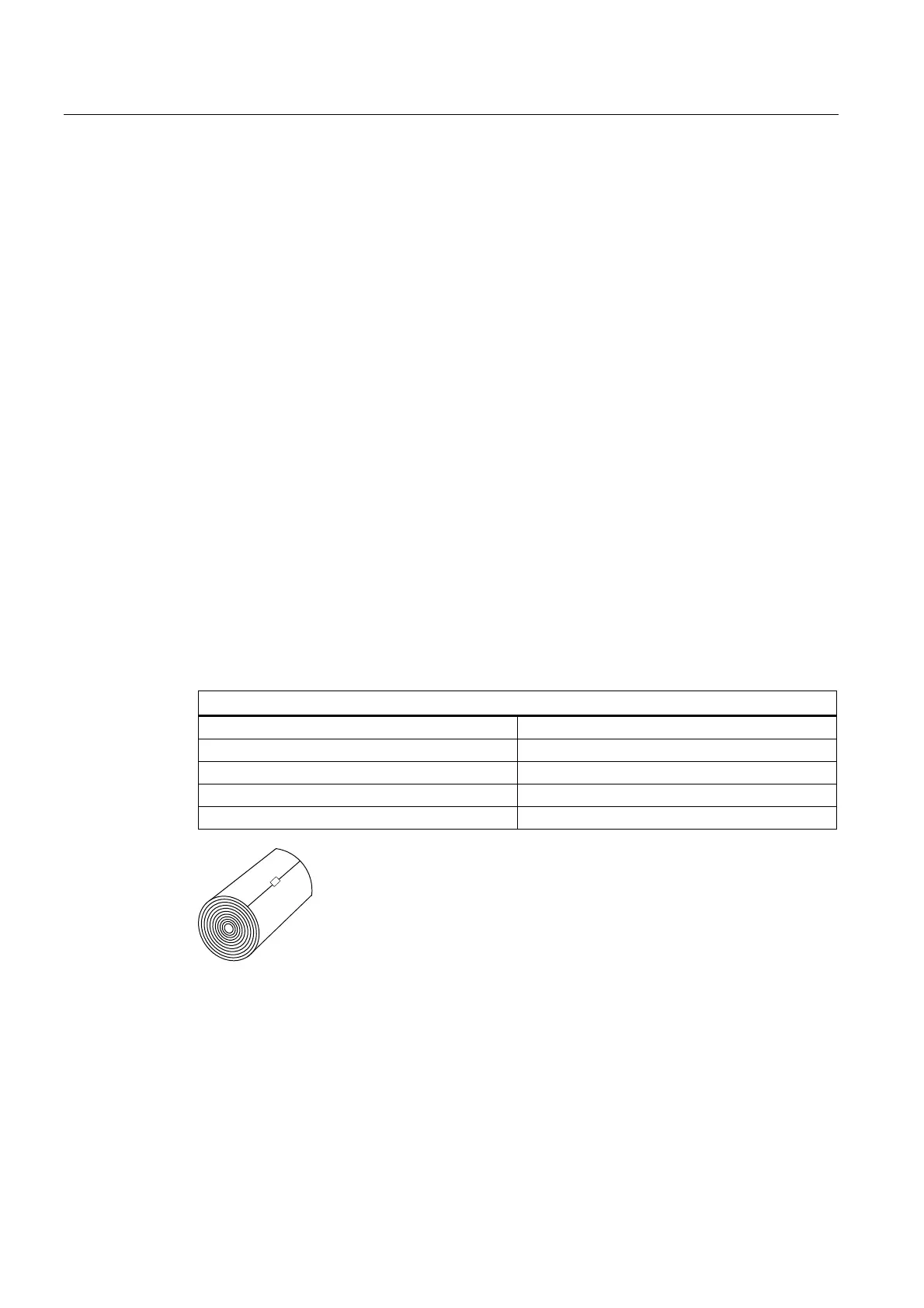
can be used. The Mylar spacing guide comes in various lengths and widths to accommodate
most pipe sizes.
Spacing Guide Sizes
Metric English
5.08cm x 66.04cm 2" x 26"
5.08cm x 114.3cm 2" x 45"
10.16cm x 393.7cm 4" x 155"
15.2cm x 497.8cm 6" x 196"
Figure 5-15 Mylar Spacing Guide
1. After receiving the spacing index from the Installation Menu, prepare the pipe surface
area where the sensors will be mounted.
2. Degrease the surface and remove any grit, corrosion, rust, loose paint, etc.
3. Make a note of the Number Index displayed in the [Install] menu. Check to ensure that
you have a matched set of sensors. They both should have the same S/N number but
marked with either an "A" or "B" (e.g., 100A and 100B).