Troubleshooting
10.4 Site Setup Data
FUS1010 IP65 NEMA 4X & IP66 NEMA 7
172 Operating Instructions, 01/2013, A5E02951520-AC
10.4 Site Setup Data
This menu provides data pertaining to sensor characteristics and operation. Some menu
items are for technical support interpretation only.
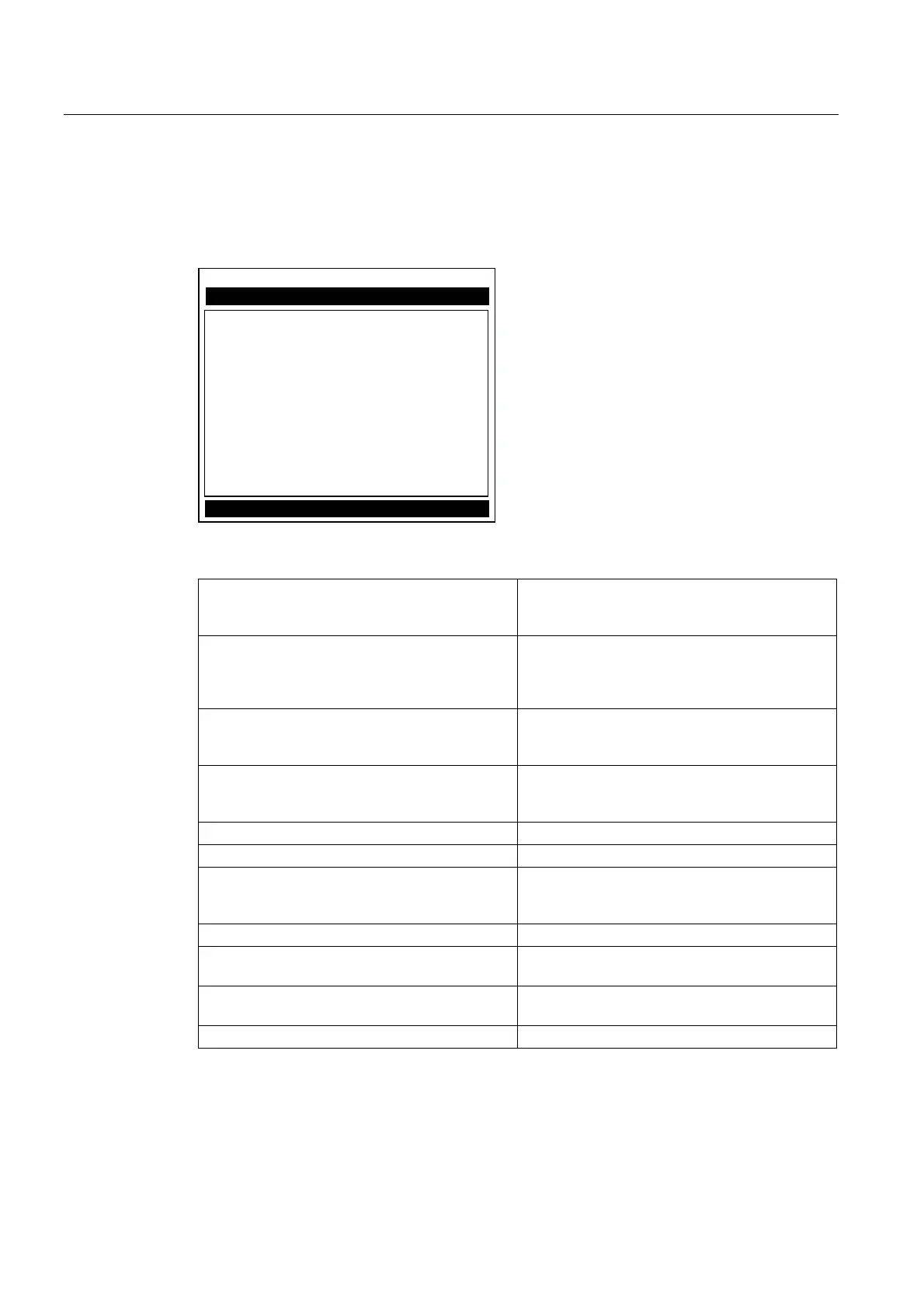
6LWH6HWXS'DWD
6LHPHQV 'XDO3DWK>@$%&
&XUUHQWWUDQVPLWGULYHFRGH
I[GULYH
1EXUVWOHQJWK
/WQ
9IPD[
9VPD[06
9VPLQ06
(PSW\
6DPSOHV&\FOH
0D['DPSLQJ
0LQ'DPSLQJ
+)
Table 10- 4 Site Setup Menu Items
fx Drive Current Transmit drive code selected during
Initial Makeup. The drive code controls the sonic
transmit signal.
N (burst length) Transmit burst duration selected during Initial
Makeup. To change N count press <Right
Arrow>. At equal sign enter numeric value (1 to 9
only).
Ltn (mm/in) Spacing distance between the sensors. It will be
in inches or millimeters, depending on default
units.
Vf max The flow velocity (in selected units)
corresponding to one whole cycle offset between
upstream and downstream receive signals.
Vs max M/S Maximum Vs for current sensor spacing.
Vs min M/S Minimum Vs for current sensor spacing.
Empty Value of Empty Alarm Setting. The meter will
declare an empty status if signal strength drops
below this value.
Samples/Cycle Digital sampling rate.
Max Damping Maximum signal damping. Use to average digital
data when an unstable condition occurs.
Min Damping Minimum signal damping. Use to average digital
data when an unstable condition occurs.
HF Flow registration correction parameter.