Connecting
5.2 Transmitter Wiring
FUS1010 IP65 NEMA 4X & IP66 NEMA 7
Operating Instructions, 01/2013, A5E02951520-AC
43
5.2.2 Wiring Temperature Sensor to Transmitter
Wiring Temperature Sensor to the Analog Input Module
DANGER
Hazard Voltage
Contact with exposed wiring will lead to fire, electric shock, or serious personal injury.
Set transmitter and instrumentation power to OFF when inserting or removing the Analog
Input Module, or when making connections to TB1, TB2, TB3 and TB4.
1. Disconnect power from the unit to the transmitter.
2. Open the transmitter top cover by releasing the cover latch.
3. Loosen the captive thumbscrew securing the Access Cover and remove Access Cover.
4. Using a flat-blade screwdriver, remove four captive screws securing the I/O board.
Remove board and set it aside.
6,(0(16
83
6,(0(16
83'1 '1
&+$11(/
&+$11(/
'8$/&+$11(/
,138702'8/(
-
7(67
21
2))
32:(5
&$87,21
+,*+92/7$*(
)86(
ಯ9
5$7,1*
$7<3(02/
$7<3(02/
86(63(&,),(')86(
5(029(&29 (5)25
$&&(667232: (5
&211(&7,216$)7(5
(;7(51$/32:(5,6
',6$%/('
(1$%/(
',6$%/(
.(<3$'
5(029(&29(5)25$&&(66
72,2:,5,1*7(50,1$/6
8/&6$&(57,),('
1
$&32:(5683 3/<
92/76
+]
6,1*/(3+$6(
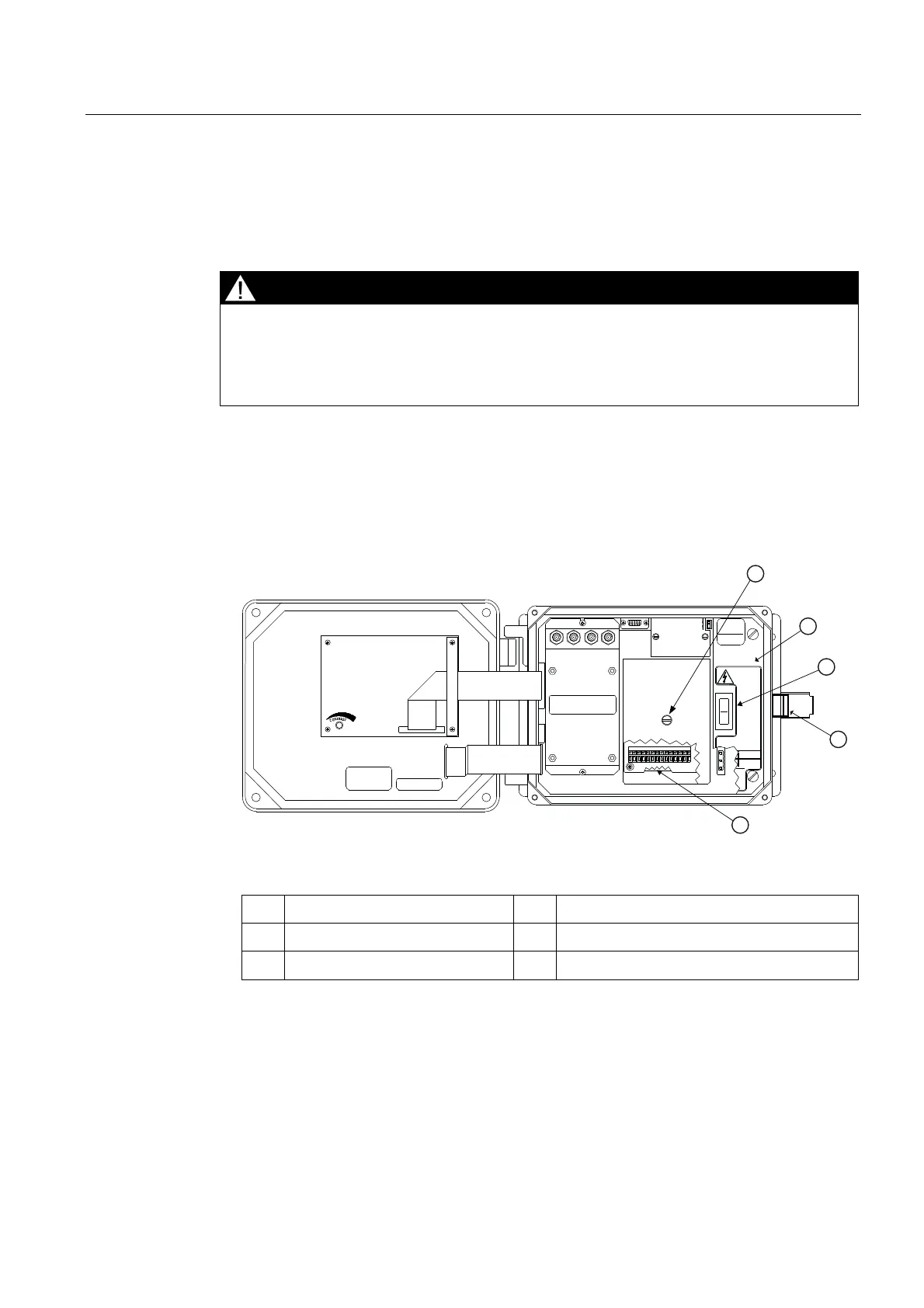
Figure 5-2 Analog Input Module Access
①
Access Cover Screw
④
Latch
②
Flow Meter
⑤
Access to Analog Input Module
③
Power Switch