Appendix
A.2 I/O Connections and Wiring
FUS1010 IP65 NEMA 4X & IP66 NEMA 7
Operating Instructions, 01/2013, A5E02951520-AC
195
Note
Relays shown in Power OFF position, whic
h is the same as the alarm assertion position.
*7ME39400AL03 Mercury Relay only available with Normally Open.
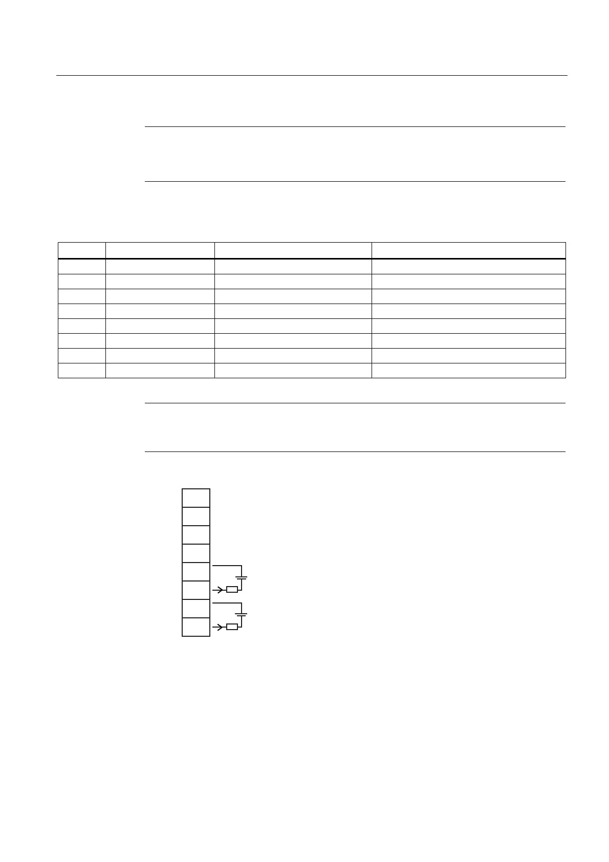
Table A- 12 Input/Output Wiring (TB4) - 7ME39400AL04 Expanded I/O Module
Pin# Signal Function Description
1 No Connection
2 No Connection
3 No Connection
4 No Connection
5 AUX 103+ Isolated Loop Supply Connect +30V max. Loop Supply here
6 AUX 103- Loop-Powered 4-20mA PGEN 1 Data Presented as 4-20mA
7 AUX 104+ Isolated Loop Supply Connect +30V max. Loop Supply here
8 AUX 104- Loop-Powered 4-20mA PGEN 2 Data Presented as 4-20mA
Note
Auxiliary 4-20mA loops are assigned and spanned under menu control of Vo and PGEN
outputs.
+
-
R
L
+
-
R
L
I
I
V
C
V
C
1
2
3
4
5
6
7
8
NC
NC
TB4
AUX Io3
AUX Io4
NC
NC
Vc: 24 VDC typical (+15 VDC to +30 VDC max) Loop Power
R
L
: 1000 ohms (max), Loop wire resistance plus user's input load resistance
I: 4-20mA