Appendix
A.2 I/O Connections and Wiring
FUS1010 IP65 NEMA 4X & IP66 NEMA 7
196 Operating Instructions, 01/2013, A5E02951520-AC
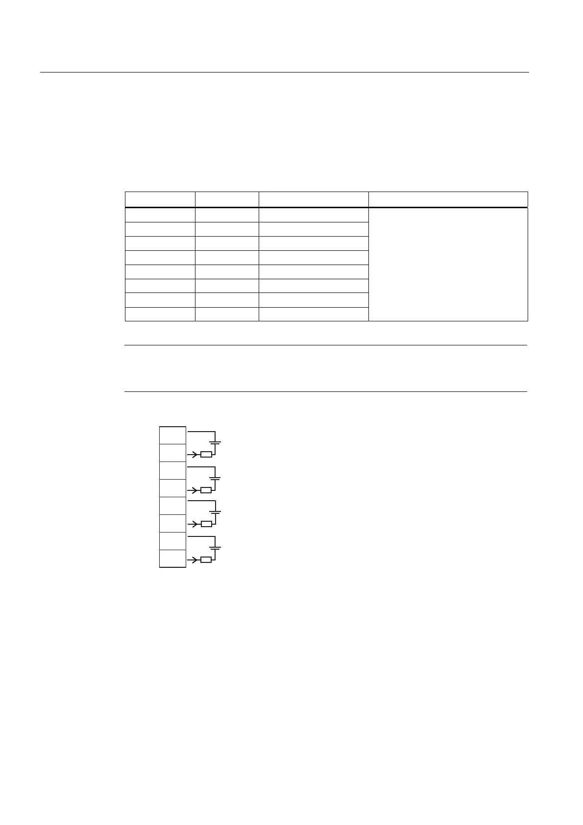
Terminal Block Wiring - 7ME39406ML00 I/O Module (4-Channel)
FUS1010, 7ME35309 only
(Refer to manual drawing 1010N-8MS2-7 (sheet 2 of 2)
Table A- 13 Input/Output Wiring (TB3) - 7ME39406ML00 I/O Module (4-Channel)
Pin# Signal Function Description
1 Iout 1+ Isolated Loop Supply
2 Iout 1- Isolated Loop Return
4-20mA proportional to spanned,
selected variable (loop power).
3 Iout 2+ Isolated Loop Supply
4 Iout 2- Isolated Loop Return
5 Iout 3+ Isolated Loop Supply
6 Iout 3- Isolated Loop Return
4-20mA o
utputs also provide a fault
indication by dropping to 2mA if
assigned to flow rate and under fault
conditions.
7 Iout 4+ Isolated Loop Supply
8 Iout 4- Isolated Loop Return
Note
Flow meter requires external power supply. Shunt as shown. Current is controlled within
loop. 4-20mA inputs and outputs are isolated.
-
+
-
R
L
+
-
R
L
I
I
V
C
V
C
+
R
L
+
-
R
L
I
I
V
C
V
C
7%
AUX Io1
AUX Io2
AUX Io3
AUX Io4
Vc = +30V (max) Loop Supply 1k ohm (max)
 Loading...


