Appendix
A.2 I/O Connections and Wiring
FUS1010 IP65 NEMA 4X & IP66 NEMA 7
182 Operating Instructions, 01/2013, A5E02951520-AC
.
. .
.
5HOD\
5HOD\
5HOD\ 5HOD\
7%
3
9ROWDJH2XWSXW
P$2XWSXW
7%
56
'LJLWDO,QSXWV
7%
-
-
3*(12XWSXW
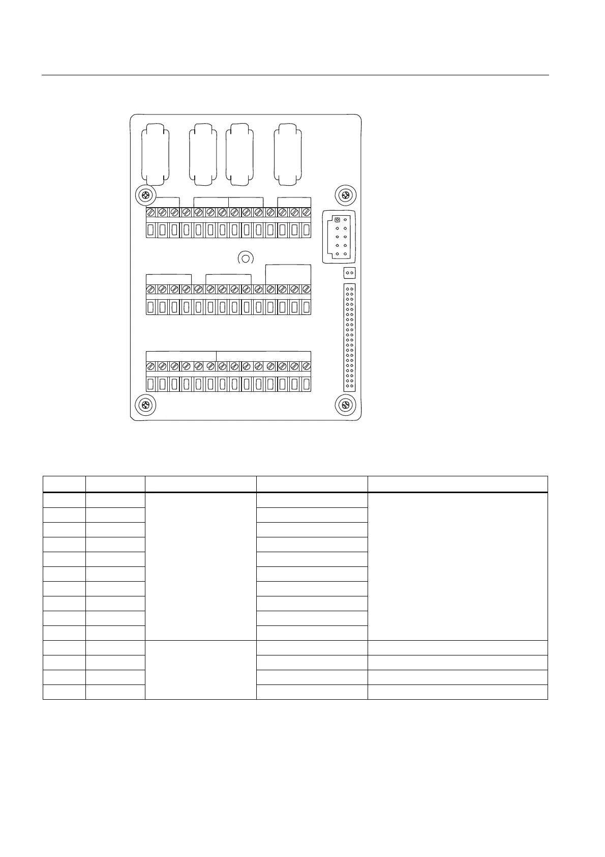
Figure A-1 7ME39400AL00 and 7ME39400AL01 I/O Module
Table A- 2 Input/Output Wiring (TB2) - 7ME39400AL00 and 7ME39400AL01 I/O Module (for 7ME3500 or 7ME3530 only)
Pin# Signal Description Definition Function
1 Vo1+ 0-10 Volt Analog Output
2 Vo1- Ref. Ground
3 Vo2+ 0-10 Volt Analog Output
4 Vo2- Ref. Ground
5 CGND Chassis GND
6 Io1+ 4-20mA Output 1
7 Io1- Isolated Return
8 Io2+ 4-20mA Output 2
9 Io2- Isolated Return
10 CGND
Meter process variables
are assigned to individual
outputs under menu
control.
System outputs assignable and scalable
to flow related parameters. CGND is for
cable shield terminations.
4-20mA outputs also provide a fault
indication by dropping to 2mA if assigned
to flow rate and under fault conditions.
Chassis GND
11 PG1 Frequency Output 1 5V TTL
12 PG2 GND GND
0 -500
0 Hz Frequency
output; assignable.
13 PG3 Frequency Output 2 5V TTL
14 PG4 GND GND