Connecting
5.5 Sensor Installation
FUS1010 IP65 NEMA 4X & IP66 NEMA 7
Operating Instructions, 01/2013, A5E02951520-AC
63
Installing the Sensor
1. Take either sensor and apply a continuous lengthwise 3mm (1/8-inch) bead of coupling
compound across the center of the sensor emitting surface.
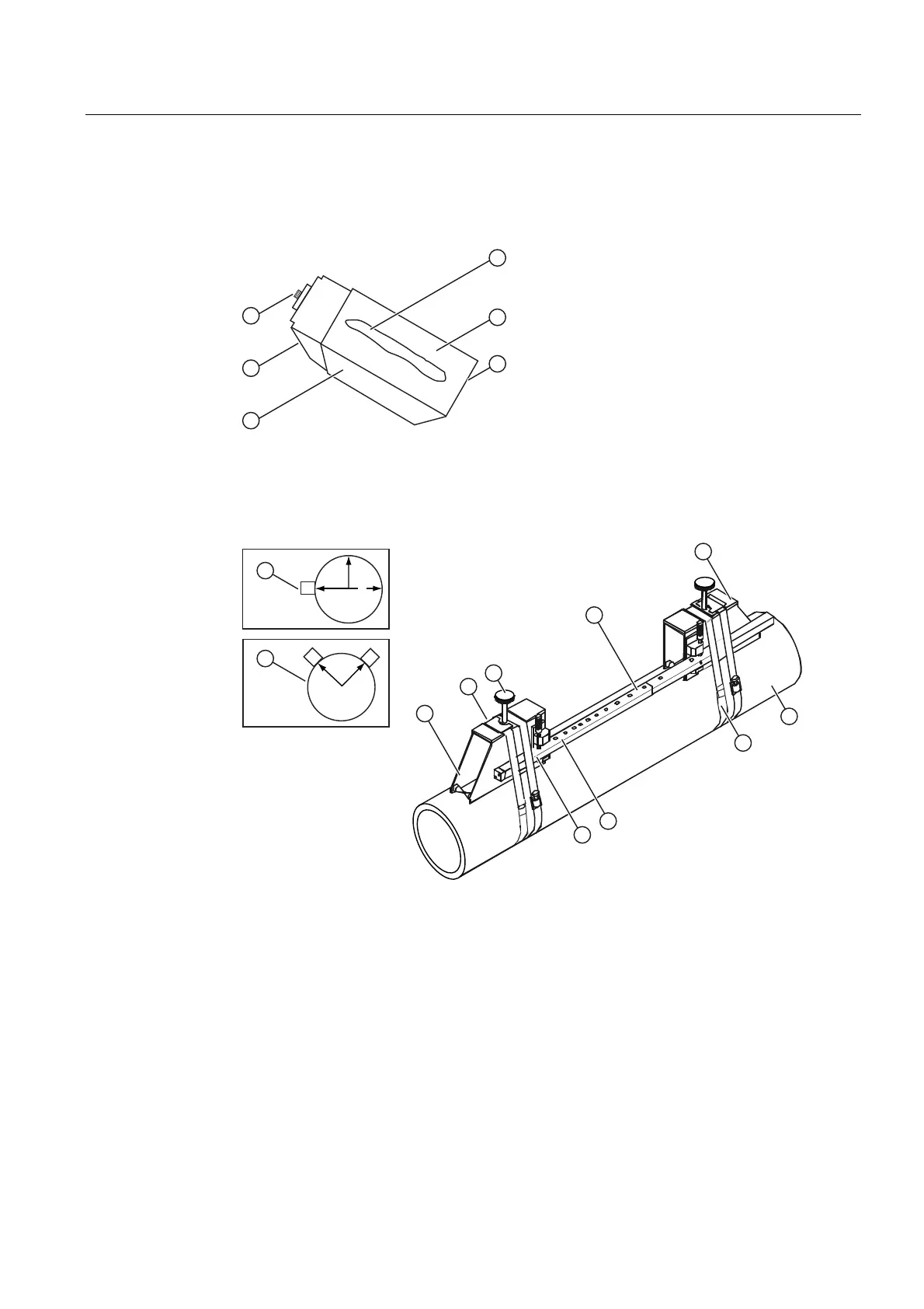
① ④ F-Connector Front Face
② Angled Edge ⑤ Emitting Surface
③ Sensor ⑥ Coupling Compound
Figure 5-13 Sensor
5()
① Front View ⑥ Pipe
② Spring Clip (Not present on some
models)
⑦ Mounting Strap Note: Optional 2nd
Mounting Strap shown. Larger pipes over
76cm (30 inches) may need an additional
support.
③ Sensor Clamping Screw ⑧ Spacer Bar Platform and Clamping
Screw
④ Spacer Bar ⑨ Spacer Bar Reference Hole
⑤ 7ME39600M Mounting Frame ⑩ Orientation for Single Beam Sensor at 9
o'clock position
⑪ Orientation for Dual Beam Sensor at 10
& 2 o'clock positions
Figure 5-14 Sensor Installation