Connecting
5.5 Sensor Installation
FUS1010 IP65 NEMA 4X & IP66 NEMA 7
70 Operating Instructions, 01/2013, A5E02951520-AC
1. Perform all required menu steps up until the point where you respond to the [Install
Complete] prompt.
2. Make note of the Number Index. Check to ensure that you have a matched set of
sensors. They both should have the same serial number but marked with either an "A" or
"B" (e.g. 100A and 100B).
Note
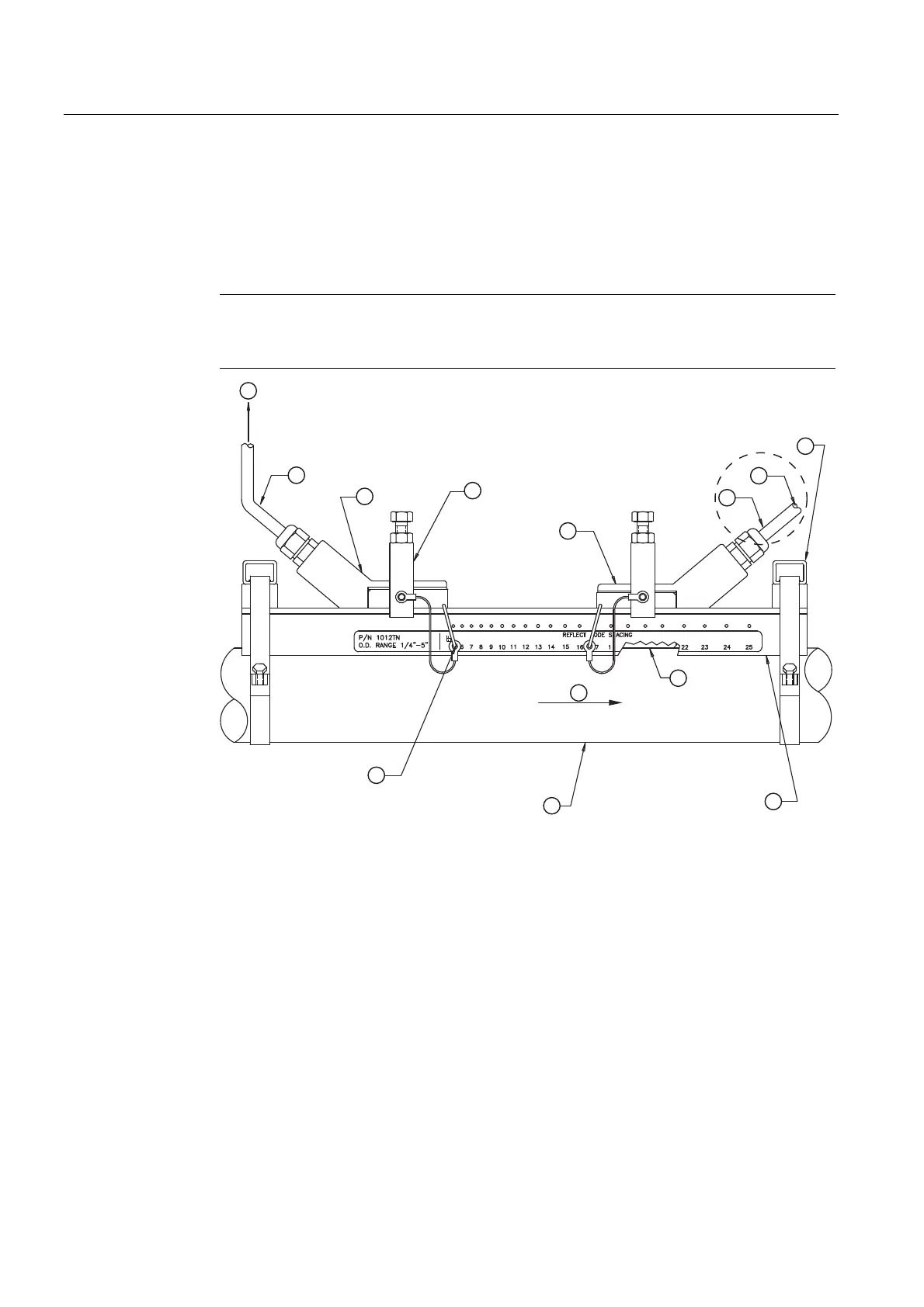
Index pins are used as stops against each sensor inserted at the reference hole for one
sensor and the Number Index hole for the other sensor (see
⑪ in figure below).
① ⑥ To SITRANS F 1010 Transmitter Mounting Strap Guide
② 7ME39600CK Series Cable (992CNF) ⑦ 7ME39600M Series Mounting Track
(1012TN, 1012TNH)
③ 7ME3950 Series Sensor Upstream ⑧ Ultrasonic Couplant
④ Sensor Clamp ⑨ Flow direction
⑤ 7ME3950 Series Sensor Downstream ⑩ Pipe
⑪ REF Hole Index Pin
Figure 5-20 Reflect Mount with Model 1012TN Mounting Track (Side View)
3. Place the track rail assembly on the top surface of the pipe at the location where you
have determined it would be mounted. Ensure that it is a smooth area without any raised
spots or seams.
4. Holding the mounting track assembly in place, loop one of the strap clamps under the
pipe, pull it around and maintain tension while slipping a link over the tension screw hook.
Tighten the tension screw enough to hold the assembly on the pipe, but still allow
rotation. Repeat for the other mounting strap.