Appendix
A.2 I/O Connections and Wiring
FUS1010 IP65 NEMA 4X & IP66 NEMA 7
Operating Instructions, 01/2013, A5E02951520-AC
197
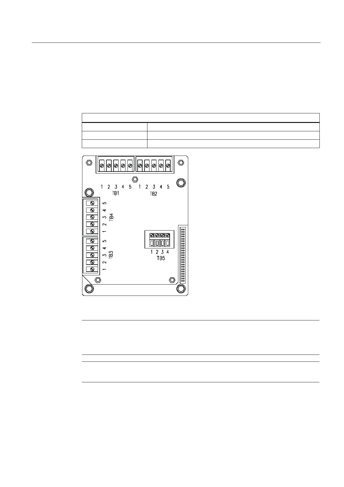
Terminal Block Wiring - 7ME39404SB00 - Analog Input Module - 2 Channel/Dual Path
(Refer to manual drawing 1010N-5DS2-7)
These connection diagrams apply to the part numbers listed below.
Table A- 14 Connection Diagrams and Part Numbers
1010N-5DS2-7 Drawing
FUS1010 7ME3530, 7ME3533
FUE1010 7ME3500
FUH1010 7ME3600, 7ME3603
Figure A-4 7ME39404SB00 Analog Input Module
Note
Use 101
2ECN series cables to connect between temperature sensor input wiring terminals
TB1 through TB4 and 991T or 1011T series temperature sensors. Note Supply and Return
temperature sensor designations when used with FUE1010 series energy flowmeter.
Note
Alternate c
olor codes for certain 1012EC cables: White = Orange Green = Brown

 Loading...


