Appendix
A.2 I/O Connections and Wiring
FUS1010 IP65 NEMA 4X & IP66 NEMA 7
190 Operating Instructions, 01/2013, A5E02951520-AC
-
+
-
R
L
+
-
R
L
I
I
V
C
V
C
+
R
L
+
-
R
L
I
I
V
C
V
C
7%
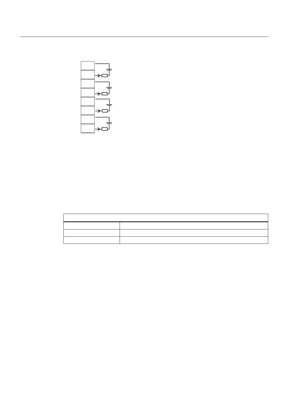
AUX Io1
AUX Io2
AUX Io3
AUX Io4
Vc: 24 VDC typical (+15VDC to 30VDC max) Loop Supply
R
L
: 1000 ohms max, = Loop wire resistance plus user's input load resistance
I: 4-20mA
Terminal Block Wiring - 7ME39400AL04 Expanded I/O Module
(Refer to manual drawing 1010N-7-7 sheet 2 of 2)
These connection diagrams apply to the part numbers listed below.
Table A- 8 Connection Diagrams and Part Numbers
1010N-7-7 (Sheet 2 of 2) Drawing
FUH1010 7ME3600, 7ME3603
FUS1010 Not Used
FUE1010 Not Used