Connecting
5.2 Transmitter Wiring
FUS1010 IP65 NEMA 4X & IP66 NEMA 7
Operating Instructions, 01/2013, A5E02951520-AC
45
Wiring Temperature Sensor Board
1. Using a flat-blade screwdriver, loosen Terminal Block TB1 and TB2 screws.
2. Wire the RTD liquid 992EC temperature cable as shown in the table below:
992EC Series Cable Terminal TB1
Wire #1 (Black) To TB1--1
Wire #2 (Orange) To TB1--2
Wire #3 (Brown) To TB1--3
Wire #4 (Red) To TB1--4
Wire #5 GND/SHLD (Blue) *To TB1--5
Note
*For cathodically protected pipes, do not attach blue #5 wire at RTD end of cable.
3. For single channel use, wire TB2 as shown in figure above.
4. For dual channel use, connect Channel 2 temperature sensor to TB2.
5. Replace I/O Board and secure with four captive screws paying careful attention to pin
alignment.
6. Replace Access Cover and finger tighten captive thumbscrew.
Note
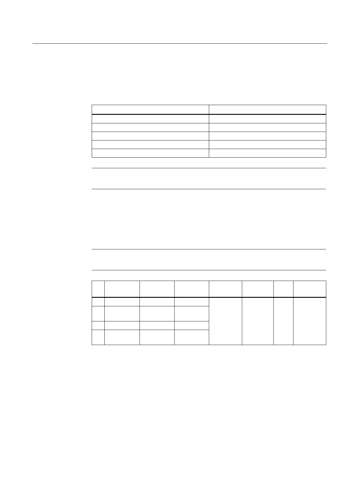
TB3 and TB4 are also active analog inputs. See wiring table below.
Pin TB3
Function
TB4
Function
Use Description Behavior Load Wiring
1 AUX. 1 IN AUX. 3 IN Iin1 Input
2 AUX. 1 COM AUX. 3
COM
Iin1
Common
3 AUX. 2 IN AUX. 4 IN Iin2 Input
4 AUX. 2 COM AUX. 4
COM
Iin2
Common
Analog
current
input
referenced
to meter
ground.
4 to 20mA 200Ω 305 meters
(1000 ft.)
Max w/o
factory
approval