Control Units, Control Unit Adapters and operating components
7.4 Control Unit CU310-2 DP (PROFIBUS)
AC Drive
290 Manual, (GH6), 04/2014, 6SL3097-4AL00-0BP4
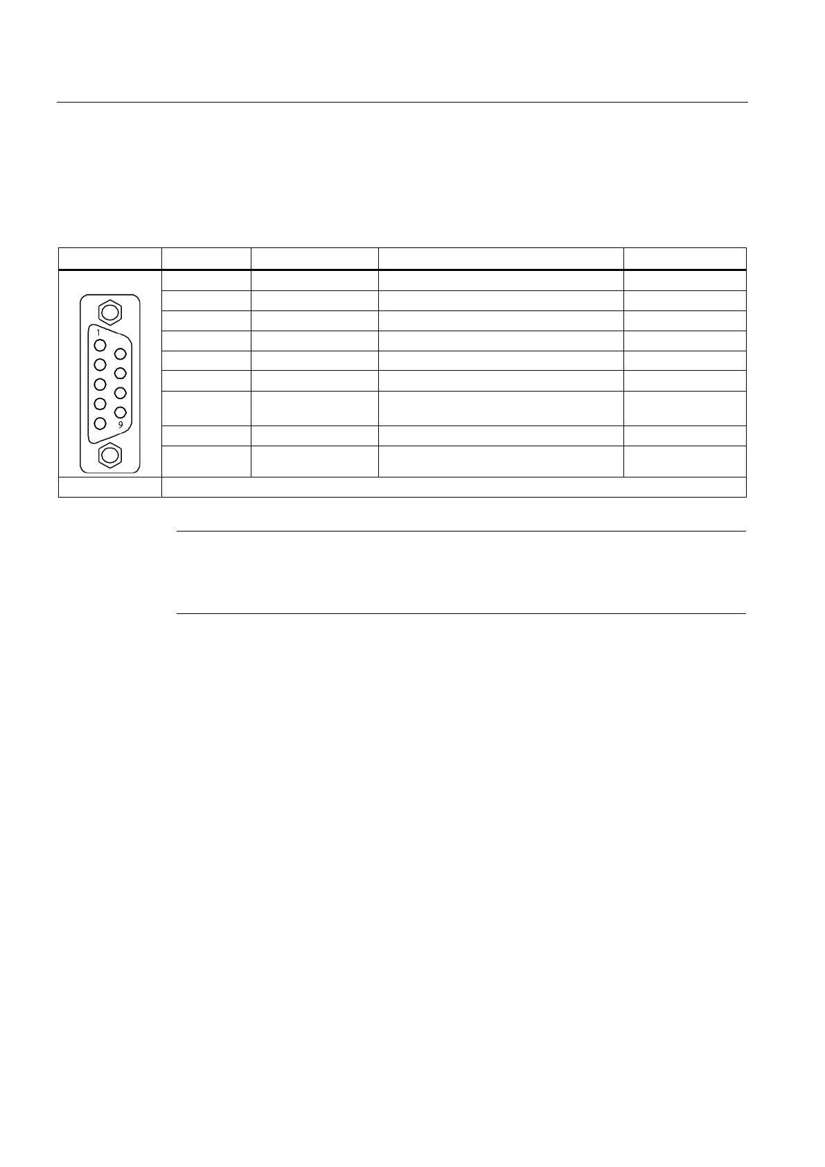
The PROFIBUS interface X21 can be operated isochronously.
Table 7- 22 X21 PROFIBUS interface
Teleservice supply, ground
Receive/transmit data P (B)
PROFIBUS data reference potential
7 P24_SERV Power supply for teleservice, + (24 V) 24 V (20.4 …
Receive/transmit data N (A)
9 - Not assigned
Note
A teleservice adapter can be connected to the PROFIBUS interface X21 for remote
diagnostics.
The power supply for the teleservic
e (terminals 2 and 7) can have a max. load of 150 mA.
For the first and last participants in a bus line, the terminating resistors must be switched in,
otherwise, data transmission will not function correctly.
The terminating resistors are activated in the connector.
The cable shield must be connected at both ends over large-surface area contacts.

 Loading...


