Control Units, Control Unit Adapters and operating components
7.5 Control Unit Adapter CUA31
AC Drive
Manual, (GH6), 04/2014, 6SL3097-4AL00-0BP4
319
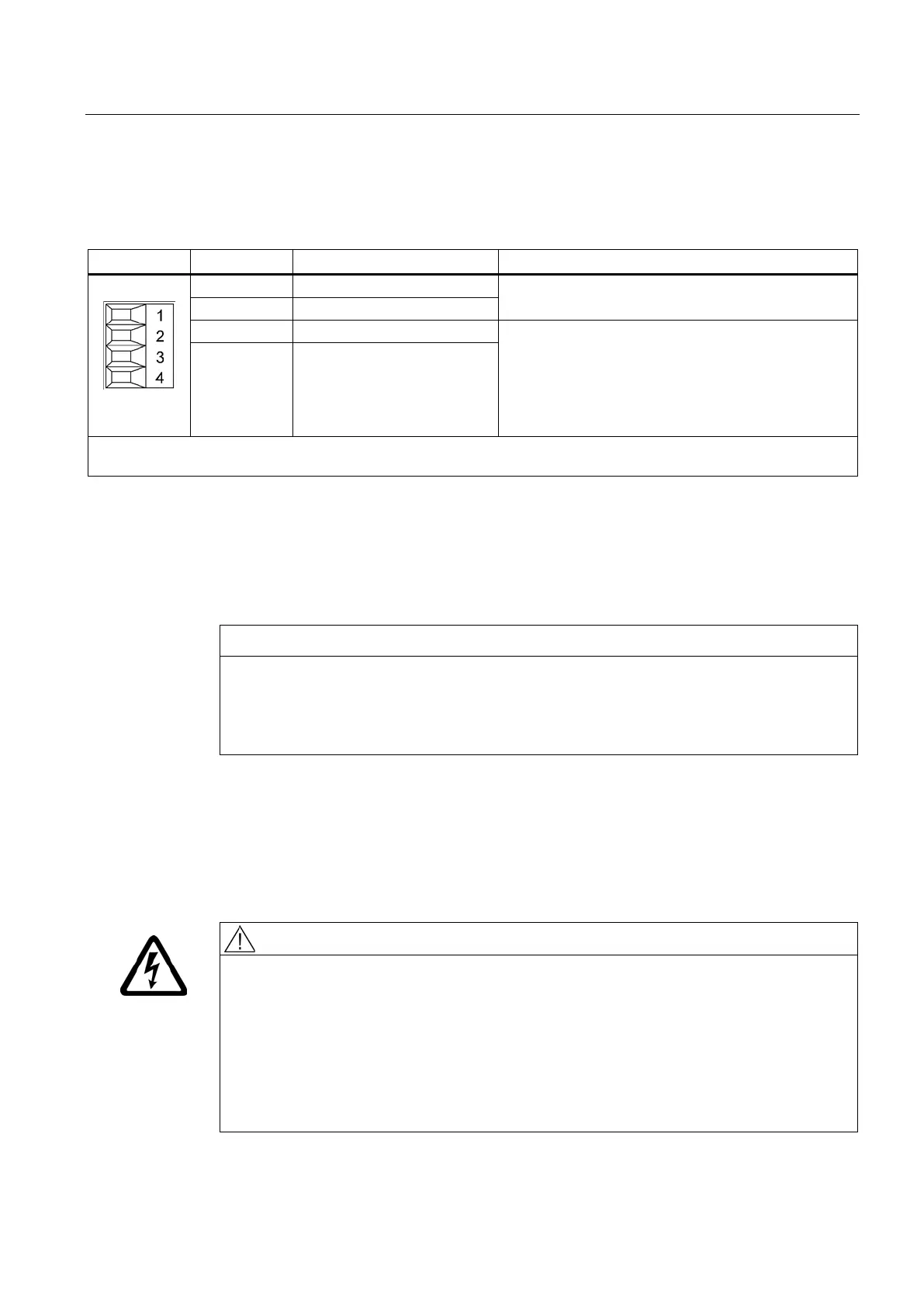
X210 EP terminal / temperature sensor
Table 7- 43 X210 EP terminal / temperature sensor input
1)
Temperature sensor KTY84–1C130/PTC
1)
Supply voltage: 24 V DC (20.4 ... 28.8 V)
Current consumption: 10 mA
Isolated input
Signal propagation delays:
L → H: 100 μs
4 EP M1 (Enable Pulses)
Type: Screw-type terminal 1 (Page 437)
Max. cross-section that can be connected 1.5 mm
2
Further information regarding the temperature sensor may be found in the SINAMICS S120 Commissioning Manual,
Section "Temperature sensors for SINAMICS components."
The temperature sensor is required for motors where the temperature value is not
transmitted via DRIVE-CLiQ.
Risk of motor overheating for incorrectly connected KTY temperature sensor
A KTY temperature sensor connected with incorrect polarity cannot detect if the motor
overheats.
• Make sure that you connect the KTY temperature sensor with the correct polarity.
The maximum length of the temperature sensor cable is 300 m. The cables must be
shielded. For cable lengths >100 m, cables with a cross-section of ≥1 mm
2
must be used.
"Safe standstill" function
If the "Safe standstill" function is selected, a 24 V DC voltage must be connected to terminals
3 and 4. Upon removal, pulse inhibit is activated.
Danger to life due to electric shock in the event of voltage flashovers at the temperature
sensor
Voltage flashovers in the signal electronics can occur in motors without safe electrical
separation of the temperature sensors.
• Use temperature sensors that fully comply with the specifications of the safety isolation.
• If safe electrical separation cannot be guaranteed (for linear motors or third-party
motors, for example), use a Sensor Module External (SME120 or SME125) or Terminal
Module TM120.

 Loading...


