Control Units, Control Unit Adapters and operating components
7.4 Control Unit CU310-2 DP (PROFIBUS)
AC Drive
Manual, (GH6), 04/2014, 6SL3097-4AL00-0BP4
303
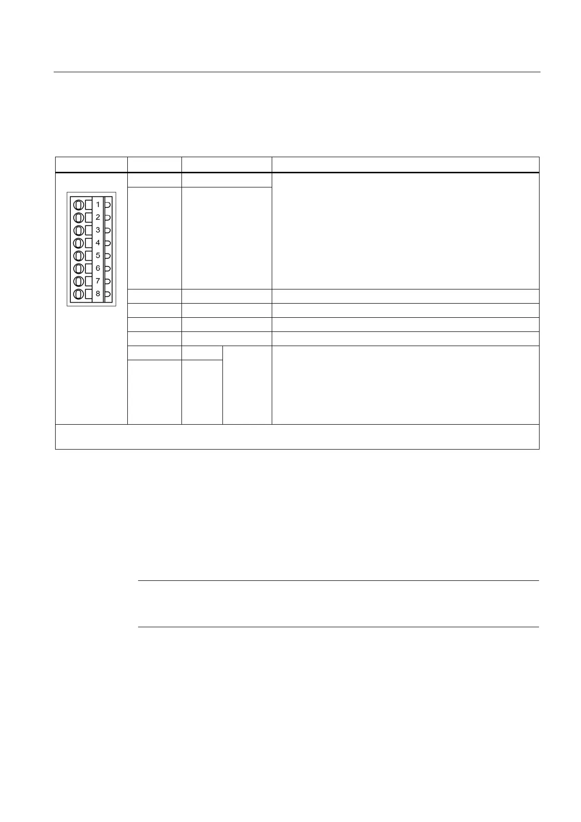
X130 digital input (fail safe) digital output
Table 7- 32 X130 digital input / fail-safe digital output
Voltage: -3 … 30 VDC
Current consumption, typical: 6 mA at 24 V
Electrical isolation: via optocoupler
Level (incl. ripple)
High level: 15 … 30 V
Low signal level: -3 … 5 V (at ≤ 2 mA)
Input delay (typ.):
For "0" → "1": 50 μs
For "1" → "0": 150 μs
protected against polarity reversal
2 DI 22-
Reference potential for digital inputs DI 0 to DI 3
Ground reference for the electronics
Reference potential for DI 16, DI 18, DI 20 and DO 16
F-DO 0
2)
Voltage: 24 VDC
Max. load current per output: 500 mA
Output delay (typ./max.):
For "0" → "1": 150 µs / 400 μs
For "1" → "0": 75 µs / 100 μs
Short-circuit, ground fault, overload proof
Automatic switch on again after overload trip
8 DO 16-
Type: Spring-loaded terminal 1 (Page 437)
Max. cross-section that can be connected: 1.5 mm
2
DI: Digital input/DO: Digital output
2)
F-DO: Fail-safe digital output
The maximum cable length that can be connected is 30 m.
The F-DO consists of a high-side switch and a low-side switch.
For applications without the safety function, the high-side switch may be used as an
additional digital output. The low side switch is not available.
V supply is briefly interrupted, the digital output is deactivated until the interruption
ified.

 Loading...


