Line Modules Booksize
3.4 Basic Line Modules with internal air cooling
Booksize power units
238 Manual, (GH2), 06/2008, 6SL3097-2AC00-0BP6
DC link connection and braking resistor connection
100 – 200 kW braking module
Note
After the the DC link voltage has been applied, fault output -X38/5 is "low" for approx.
2 seconds (self test), i.e. in the fault state.
The control unit must suppress this state when switching on the system.
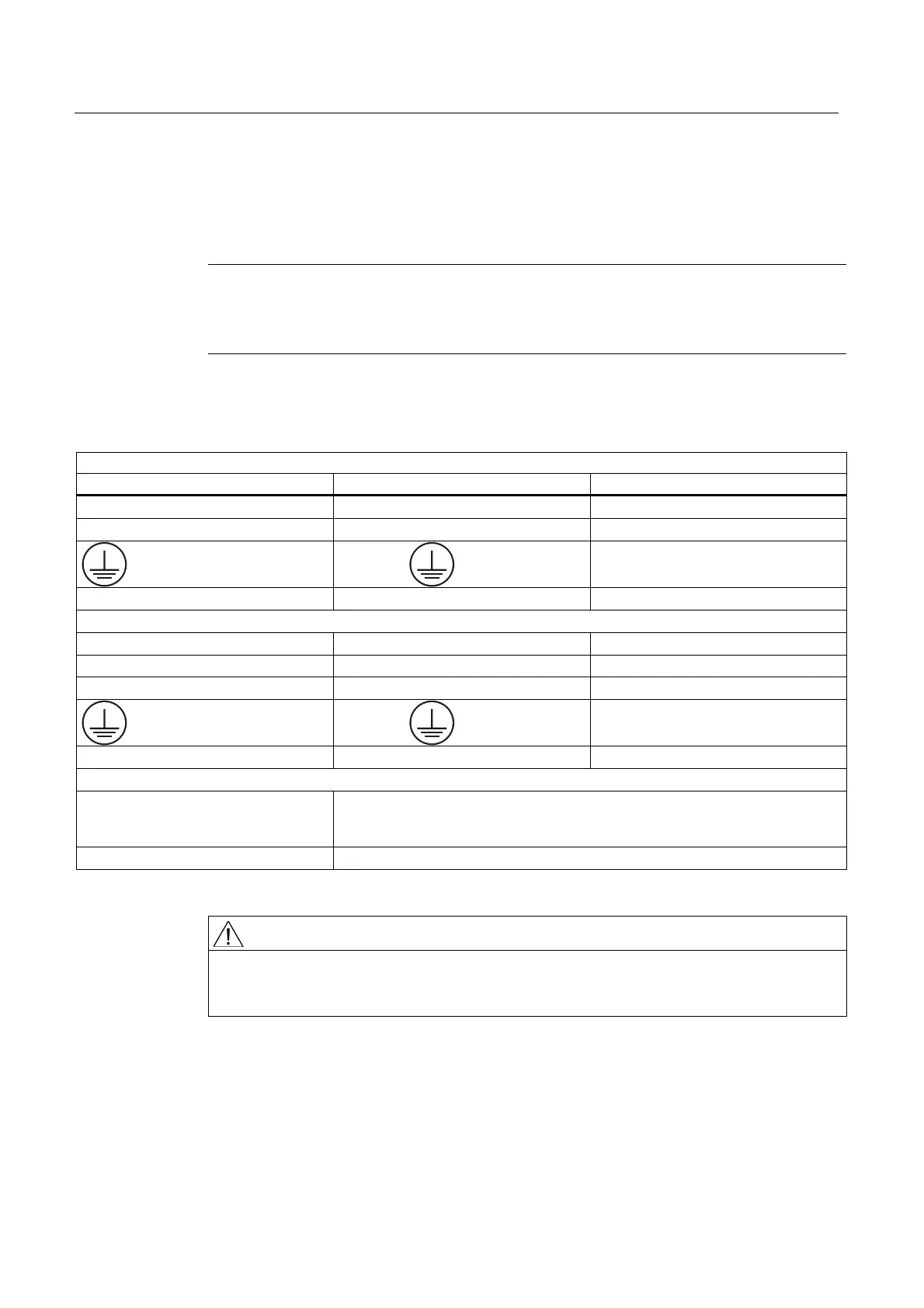
Table 3-36 Power terminals of braking modules 100 - 200 kW
DC link connection (via busbars, 100 - 200 kW)
Connection/significance Remarks Tightening torque [Nm]
C/L+ input (plus DC link) Busbar C/L+ 16
D/L- input (minus DC link) Busbar D/L 16
Protective conductor Busbar PE
16
Shield connection M6 bolts at top of housing 8
Braking resistor connection (via busbars, 100 - 200 kW)
Connection/significance. Remarks Tightening torque [Nm]
G/R+ external braking resistor Busbar G/R+ 16
H/R external braking resistor Busbar H/R 16
Protective conductor Busbar PE
16
Shield connection M6 bolts at bottom of housing 8
NOTE
Connection via Crimping cable lug to DIN 46234
With shrinkdown plastic tubing pulled over it
Cables connected with supplied M8 x 25 screws
AWG max 2/ 0
WARNING
The braking module can be connected to the DC link with or without fuses. The connections
between the converter and inverter and braking module must be short-circuit and ground-
fault resistant. The electric strength of the cable must be rated to the line voltage.
Fuses
● Fuses are required for multi-motor systems with a shared DC link (infeed power >>
power of the braking module).
● House-hold type MCBs (1000 V) must be installed in the plus and minus branches.

 Loading...


