Section09BODY/FRAME
Subsection 02 (FRAME)
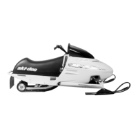
A35H0QA
1
1. Torque to 7.5 N•m(66lbf•in)
Install all other removed parts. Refer to specif-
ic sections for inspection, installation and adjust-
ment.
Engine Support
LH Support
Unscrew engine and lift it.
Remove the countershaft and its bearing. Refer
to CHAINCASE.
Remove the LH handle support.
Drill rivets holding engine support to frame.
Unscrew both engine support bolts. Note bolts's
location.
Remove engine support.
To install a new or existing engine support, reverse
the removal procedure. However, pay attention to
the following.
Install engine support bolts with heads inside.
Replace rivets with the following fasteners:
QUANTITY FASTENERS DESCRIPTION
4
Hexagonal flanged bolt M6 x 20
(P/N 207 662 044)
4
Elastic flanged nut M6
(P/N 233 261 414)
Install new bolts with their heads outside.
Install all removed parts. Refer to CHAINCASE to
install and adjust countershaft properly.
RH Support
Unscrew engine and lift it.
Remove the RH handle support.
Remove chaincase housing. Refer to CHAIN-
CASE.
Drill all rivets holding engine support to frame.
To install a new or existing engine support, reverse
the removal procedure. However, pay attention to
the following.
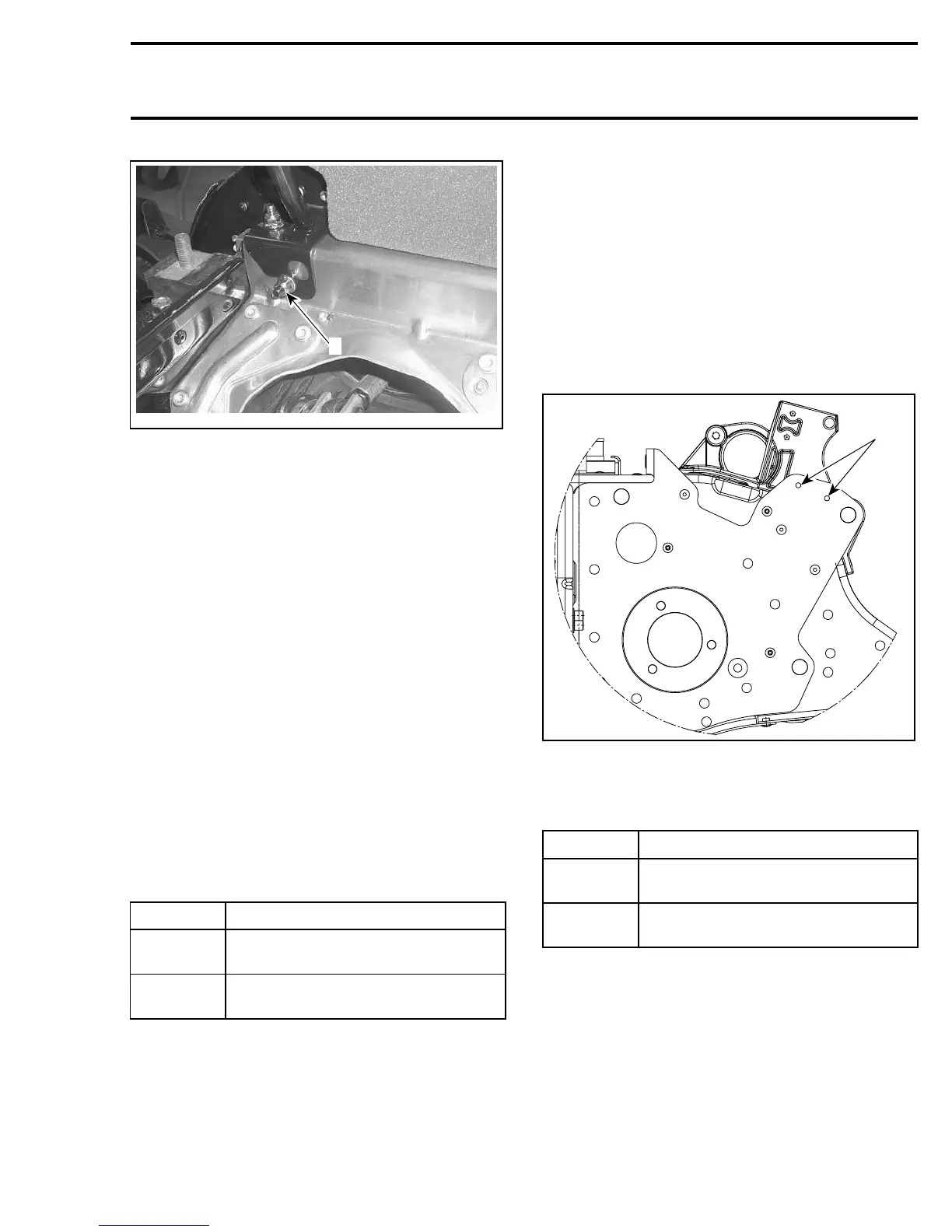
Position engine support by installing 2 pop rivets.
1
A35H0RA
1. Pop rivets
Replace all other rivets with the following fasten-
ers:
QUANTITY FASTENERS DESCRIPTION
3
Hexagonal flanged bolt M6 x 20
(P/N 207 662 044)
3
Elastic flanged nut M6
(P/N 233 261 414)
Install new bolts with the head inside.
Install all removed parts.
mmr2005-144 315