14.5 WATER SYSTEM SETUP
Refer to the installation scheme for the device dimensions, technical requirements and positioning of the
water drainage system – refer to Doc. “Installation Requirements”. Key to the abbreviations used for water
connections:
Cold water tube – cw (cold water)
Hot water tube – hw (hot water)
Pressure demineralized water tube – dw (demineralized water)
Machine Drainage tube – d (drain)
[FD (floor drain) for the floor drain connection]
14.5.1 WATER LOAD
The machine is equipped with three charging hoses.
The hoses connect to taps with threaded bushing 3/4’’ gas.
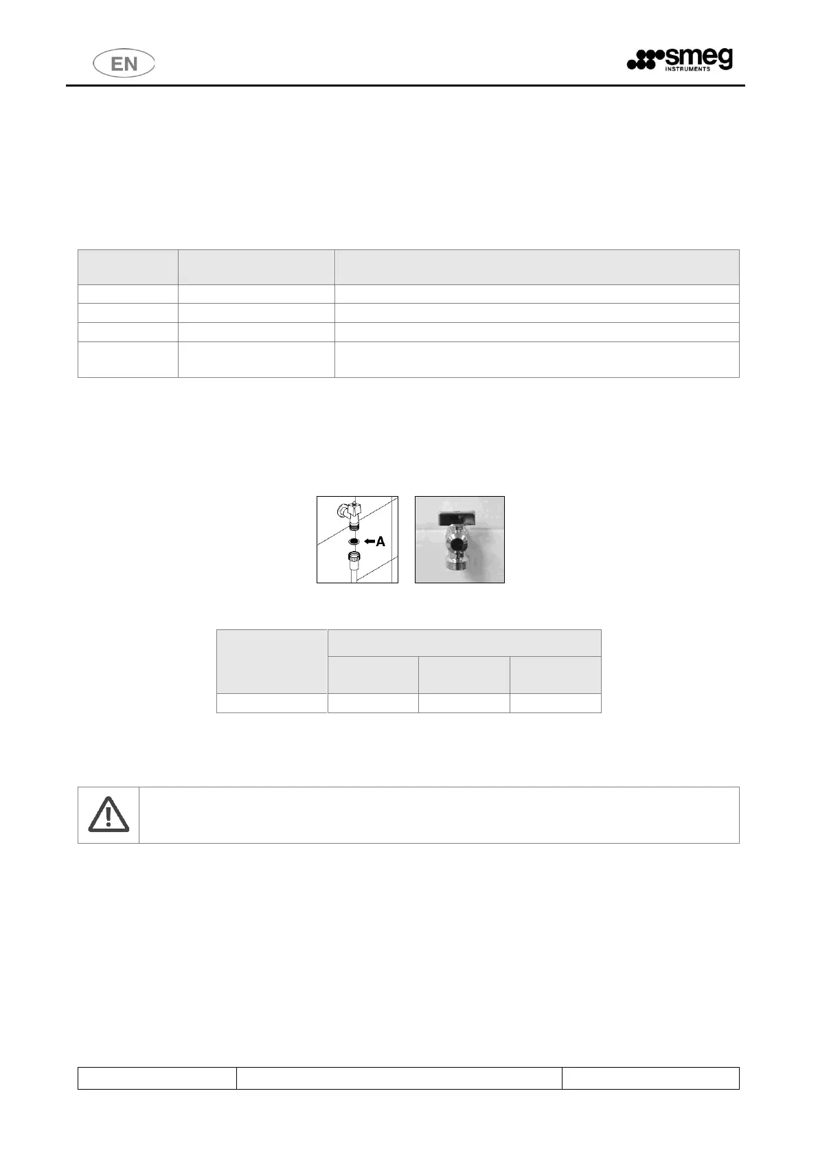
Use the supplied filter “A” in the image below to connect the charging hose end.
fig. 8 – to connect the charging hose insert the supplied filters.
TOT. NUMB.
LOAD
CONNECTIONS
POSITIONING THE INLET VALVES: The water inlet taps must be placed next to the device so that they can be
easily reached by the user.
WARNING
Valves and hoses should be placed in such a way that the removal of the hoses from the valves,
for service procedures, does not cause water spilling on the device.
Note to prevent clogging or damage risk: In the event that the water piping system is new or has not been
used for a long time, check that the water is clean and free from contaminants before connecting it to the
water supply.
If there is not a double supply of hot / cold water, the two supply pipes (cw and hw) must be connected
through the “Y” pipe fitting (see image below).



 To Next Page