201
you turn clockwise, and increase as you turn
counterclockwise.
Transforming an image using trackball/Z-ring
op
erations
You can transform an image as follows using trackball/
Z-ring operations for each three-dimensional transform.
Device control block display
In the device control block of the ICP-X7000, the display
sho
ws the following information.
• Reference DME channel name: DME1 to DME4
• Selected three-dimensional space: LOCAL, GLB and
SR
C, TRGT
• Selected parameter name: ASP PERS, LOC SIZE, LOC
X
YZ, ROT, AXIS LOC, SPIN, SKEW
• X-axis, Y-axis, and Z-axis settings
Transforming an image in three-
dimensional space
1
Press the [DME] button.
The [DME] button is lit amber, and the device control
bl
ock switches to three-dimensional transform
operation mode.
2
Using the channel selection buttons, select the target
channel (CH1 to CH4) for operation.
You can select multiple channels. The first selected
but
ton becomes the reference channel, and is lit
green. Subsequent selected buttons are lit amber.
3
Select a three-dimensional space.
[LOCAL] button: L
ocal space
[GLB] button: Gl
obal space
Both local space and global space can be selected.
[SRC] button: Sou
rce space
[TRGT] button: T
arget space
Either source space or target space can be selected.
4
Select a three-dimensional transform operation and
transform the image.
For details about three-dimensional transform
ope
rations, see “Three-dimensional transform
operation mode” (page 199).
To finely adjust the setting values of parameters
Press the [FINE] button, turning it on.
The adjustment mode switches to fine mode, enabling
f
ine adjustment of setting values using the trackball/
Z-ring.
To restrict the parameters targeted by the
op
eration
Press the [X] button, [Y] button, or [Z] button,
tu
rning it on.
This enables operation only for the selected axis
usi
ng the trackball/Z-ring.
To adjust the setting values of parameters using
th
e numeric keypad control block
You can press the [X] button, [Y] button, or [Z] button in
th
e device control block to display the name and value of
parameters on the display of the numeric keypad control
block and then set the X-axis, Y-axis, and Z-axis
parameters. Enter a value in the numeric keypad area and
press the [ENTER] button to apply the setting.
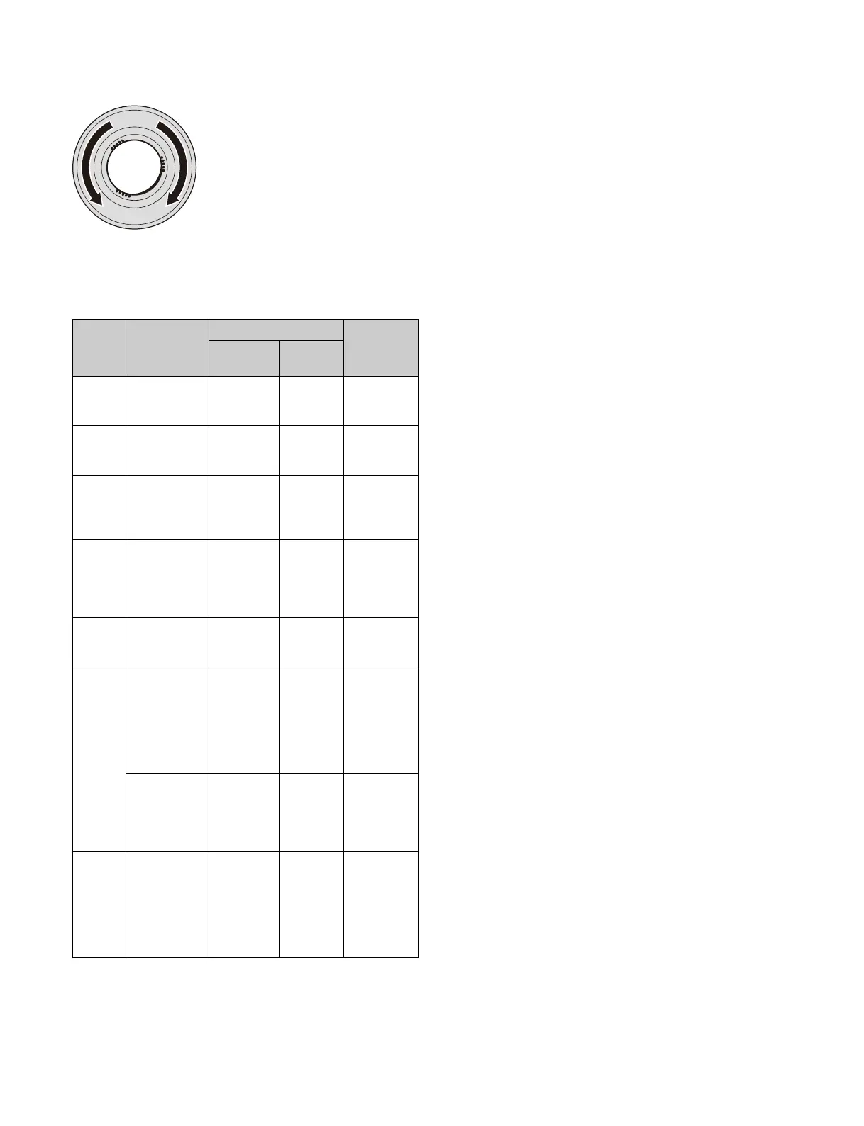
Button Three-
dimensional
space
Trackball Z-ring
Horizontal
direction
Vertical
direction
LOC
XYZ
Source/target
space
Movement
in X-axis
direction
Movement
in Y-axis
direction
Movement in
Z-axis
direction
ROT Source/target
space
Rotation
around
Y-axi
s
Rotation
around
X-axis
Rotation
around
Z-axis
SHIFT +
ROT
Source/target
space
Rotation
around
Y-axi
s
(Spin)
Rotation
around
X-axis
(Spin)
Rotation
around
Z-axis (Spin)
AXIS
LOC
Source space Move
rotation axis
in X
-axis
direction
Move
rotation
axis in
Y-
axis
direction
Move
rotation axis
in Z-axis
direction
LOC
SIZE
Source/target
space
Movement
in X
-axis
direction
Movement
in Y
-axis
direction
Scaling
(shrink/
magnify)
ASP
PERS
Source space Change
aspect ratio
in X
-axis
direction
Change
aspect
ratio in
Y-axis
direction
Simultaneous
change
aspect ratio in
X-axis
direction and
Y-axis
direction
Target space Change
viewpoint
position in
X-axi
s
direction
Change
viewpoint
position in
Y-axis
direction
Change
distance
from
viewpoint
position
SHIFT +
ASP
PERS
Source space Change
skew in
X-axis
direction
(Skew)
Change
skew in
Y-
axis
direction
(Skew)
Simultaneous
change
aspect ratio in
X-axis
direction and
Y-axis
direction
 Loading...


