375
• In through mode, only outputs 1 and multiples of 4 + 1
(1, 5, 9, and so on) can be configured.
• Ancillary data is deleted from the signals on inputs 1
an
d multiples of 4 + 1 (1, 5, 9, and so on).
• In a 1M/E box switcher configuration, ancillary data is
de
leted in the following cases.
1
Open the Home > Setup > System > Output > Output
Assign menu (19101.41).
2
Select the target output to set.
To select and set multiple outputs, place a check mark
be
side the target outputs to set.
To select and set all outputs, place a check mark in the
S
elect All checkbox.
3
Enable/disable through mode using the [Through
Mode] switch.
On:
Enable through mode.
Off: Disa
ble through mode.
Setting the Video Clip Function
1
Open the Home > Setup > System > Output > Video
Adjust menu (19101.42).
2
Select a tab to switch the target to set.
[Output] tab: Ou
tput video clip settings
[Dedicated Out] tab: Dedi
cated output video clip
settings
3
Select the target output to set and set the following
parameters.
To return the settings to the defaults
Press the [Reset] button.
Setting the Safe Title Area
1
Open the Home > Setup > System > Output > Safe
Title menu (19101.43).
2
Select a tab to switch the target to set.
[Output] tab: Ou
tput safe title settings
[Dedicated Out] tab: Ded
icated output safe title
settings
3
Select the target output to set.
4
Set the safe title area display method.
To display box 1
Set the [Box1] button to the on state.
Set the following parameter.
In the [Box1 Adjust] group, select an aspect ratio
(
16:9, 14:9, 4:3).
To display box 2
Set the [Box2] button to the on state.
Set the following parameters.
In the [Box2 Adjust] group, select an aspect ratio
(
16:9, 14:9, 4:3).
To display a cross
Set the [Cross] button to the on state.
To display a grid
Set the [Grid] button to the on state.
In the [Grid Adjust] group, select an aspect ratio
(
16:9, 4:3).
In the [Grid Size] group, select a size (80.00%,
85.
00%, 90.00%, 100.00%).
To return the settings to the defaults
Press the [Reset] button.
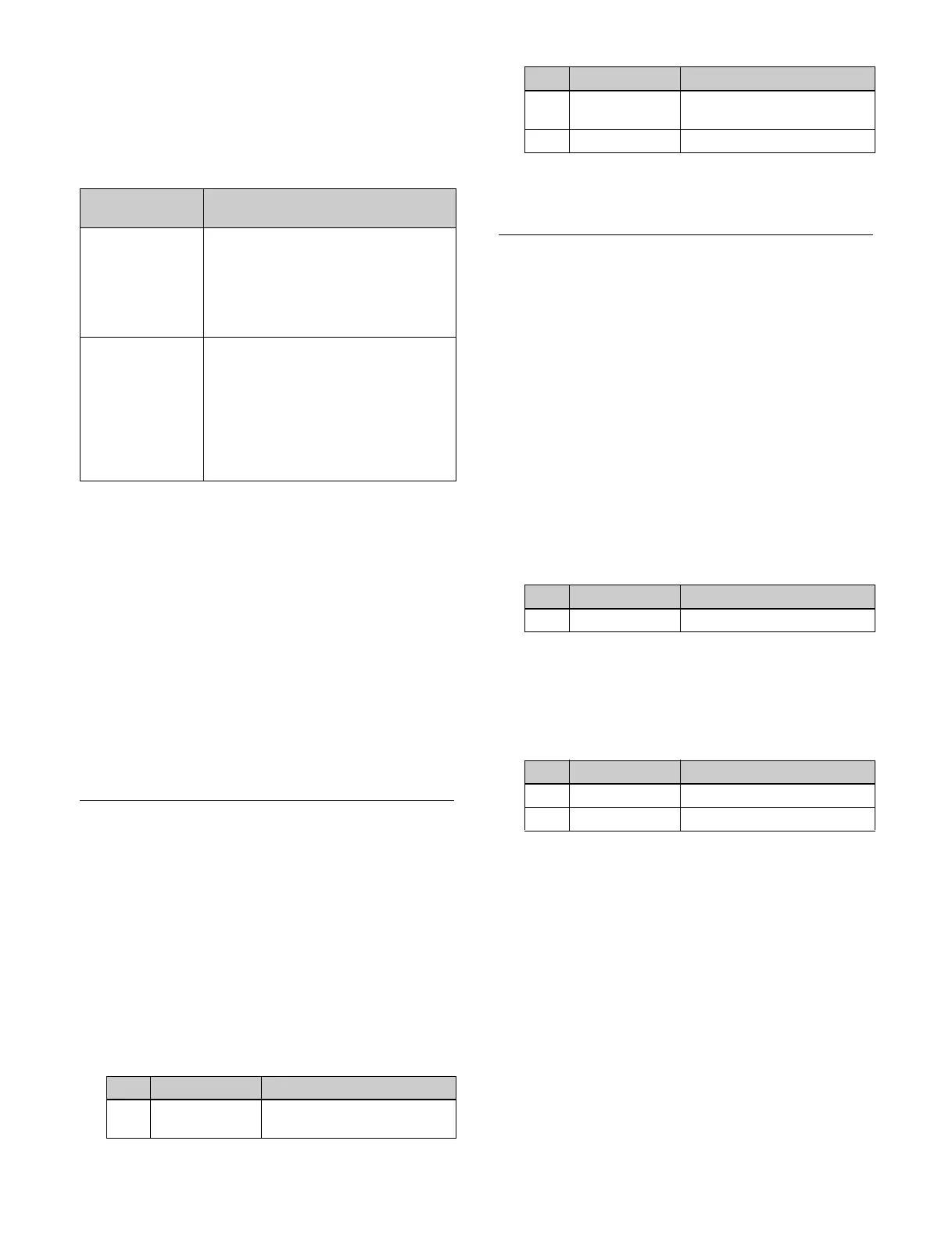
System signal
format
Output conditions
2160P • When signals on port numbers 1, 5,
9
, and 13 are output on port numbers
17, 21, 25, and 29
• When signals on port numbers 17,
2
1, 25, and 29 are output on port
numbers 1, 5, 9, and 13
1080P, 1080i • When signals on port numbers 1, 5,
9,
13, 17, 21, 25, 29, and 32 are
output on port numbers 33, 37, 41,
45, 49, 53, 57, and 61
• When signals on port numbers 33,
3
7, 41, 45, 49, 53, 57, and 61 are
output on port numbers 1, 5, 9, 13,
17, 21, 25, 29, and 32
No. Parameter Adjustment
1 White Clip Luminance signal white clip
va
lue
2 Dark Clip Luminance signal dark clip
value
3 Chroma Clip Chrominance signal clip value
No. Parameter Adjustment
1 Size Size
No. Parameter Adjustment
1 Size Size
2 Luminance Luminance
No. Parameter Adjustment
 Loading...


