Chapter 18 System Setup (System)
1074
System Settings (System Config Menu)
Special system setting (Single Simul mode)
When using a combination of a 4M/E switcher processor and a 4-channel DME
processor in an HD system, the Single Simul mode is available. In this mode,
M/E-1 on the switcher processor is linked to M/E-3, and M/E-2 is linked to P/
P. As a result, the M/E-1 and M/E-2 panel buttons go off, and cannot be
operated.
In this mode, the screen aspect ratio is fixed, as follows.
Relation between switcher and DME: Operations are linked with the screen
aspect ratios the same.
Notes
• The waveforms for wipe pattern numbers 23, 24, 26, and 27 are the same
in 4:3 and 16:9 modes.
• Color backgrounds, frame memory, and other functions used on the
whole switcher operate at 16:9.
Note on creating a user programmable DME: The keyframe registers used
for creating a user programmable DME are divided by screen aspect ratio
as shown in the following table.
The actual operation is linked between the top and bottom rows of the table
(e.g. M/E-3 and M/E-1), but the common setting values cannot be used
between the two screen aspect ratios. The edges of the screen, for example,
differ between 16:9 and 4:3.
For image operations in the device control block, first make the settings
separately on the different channels.
Recalling a user programmable DME: When recalling a user programmable
DME, select pattern numbers 1901 to 1949, 2901 to 2949, or 3901 to 3949.
The effects for the 16:9 and 4:3 screen aspect ratios will be recalled linked
together.
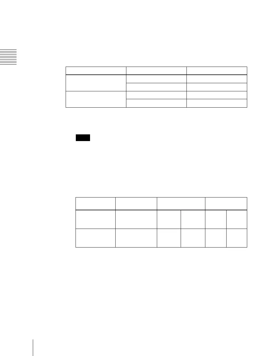
Processor Bank or channel Screen aspect ratio
Switcher processor M/E-3 and P/P 16:9
M/E-1 and M/E-2 4:3
DME processor Channels 1 and 2 16:9
Channels 3 and 4 4:3
Register
numbers
Screen aspect
ratio
Switcher bank Channel
101 to 149,
201 to 249,
301 to 349
16:9 M/E-3 P/P Ch1 Ch2
151 to 199,
251 to 299,
351 to 399
4:3 M/E-1 M/E-2 Ch3 Ch4

 Loading...


