Power Unit Mechanical: 1D-18
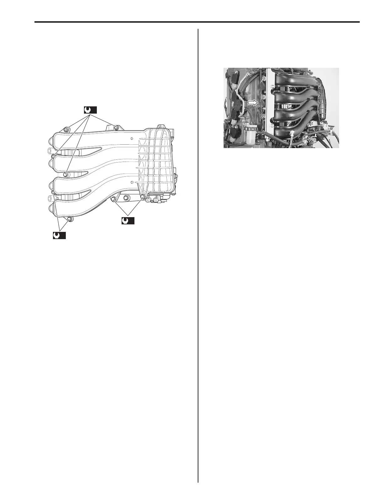
Intake manifold
• Install gaskets and intake manifold, then tighten bolts
and nuts to specified torque.
Refer to “Intake Manifold Removal and Installation”
(Page 1D-7).
Tightening torque
Intake manifold bolt / nut (8 mm) (a): 23 N·m (2.3
kgf-m, 16.5 lbf-ft)
Fuel injectors
• Install fuel injectors and fuel delivery pipe.
Refer to “Fuel Injector Removal and Installation” in
Section 1G (Page 1G-23).
Perform the following final assembly checks to
ensure proper and safe operation.
• All parts removed have been returned to their original
positions.
• Fuel and water hose routing matches service manual
illustration.
Refer to “Fuel Hose Routing” in Section 4B (Page 4B-
1) and “Water Hose Routing” in Section 4B (Page 4B-
5).
• Wire routing matches service manual illustration.
Refer to “Wiring Harness Routing Diagram” in Section
4A (Page 4A-3).
• No fuel leakage is evident when fuel system is
pressurized.
Refer to “Fuel Leakage Check Procedure” in Section
1G (Page 1G-16).
• No water leakage is evident during final test running.
(a)
(a)
(a)
I9J011140164-01
I9J011140165-01