Power Unit Mechanical: 1D-22
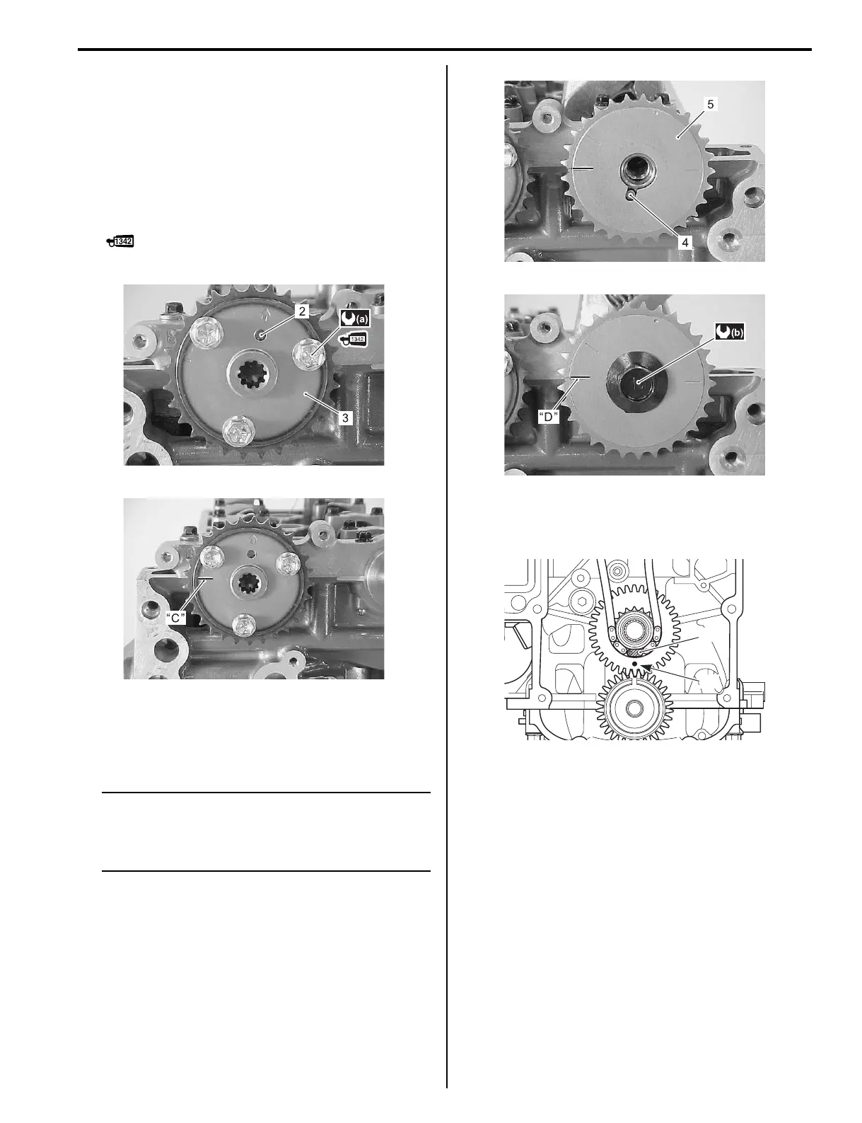
3) Fit the dowel pin (2) onto EX. camshaft.
Install EX. camshaft timing sprocket (3), then tighten
sprocket bolts, pre-coated with thread lock, to
specified torque.
Check that engraved line “C” on sprocket is correctly
aligned with mating face of cylinder head cover.
Tightening torque
EX. timing sprocket bolt (a): 11 N·m (1.1 kgf-m,
8.0 lbf-ft)
: Thread lock cement 99000–32050
(SUZUKI Thread Lock 1342 (50 g))
4) Install dowel pin (4) and IN. camshaft timing sprocket
(5), then tighten sprocket bolt to specified torque.
Check that engraved line “D” on sprocket is correctly
aligned with mating face of cylinder head cover.
NOTE
When installing camshaft sprocket, position
side of sprocket with two engraved lines
facing down toward engine holder as shown
figure.
Tightening torque
IN. timing sprocket bolt (b): 78 N·m (7.8 kgf-m,
56 lbf-ft)
5) As shown in figure, position timing chain on driven
gear sprocket with yellow plate “H” of chain aligned
with match mark “B” on driven gear.
6) As shown in figure, engage timing chain with
exhaust sprocket with one BLUE plate “I” of chain
aligned with match mark (arrow) “E” of exhaust
sprocket.
7) As shown in figure, engage timing chain with intake
sprocket with another BLUE plate “I” of chain aligned
with match mark (•) “F” of intake sprocket.
I9J011140173-01
I9J011140174-02
I9J011140175-02
I9J011140176-03
“H”
“B”
I9J011140026-01