1D-59 Power Unit Mechanical:
3) Install crankshaft to cylinder.
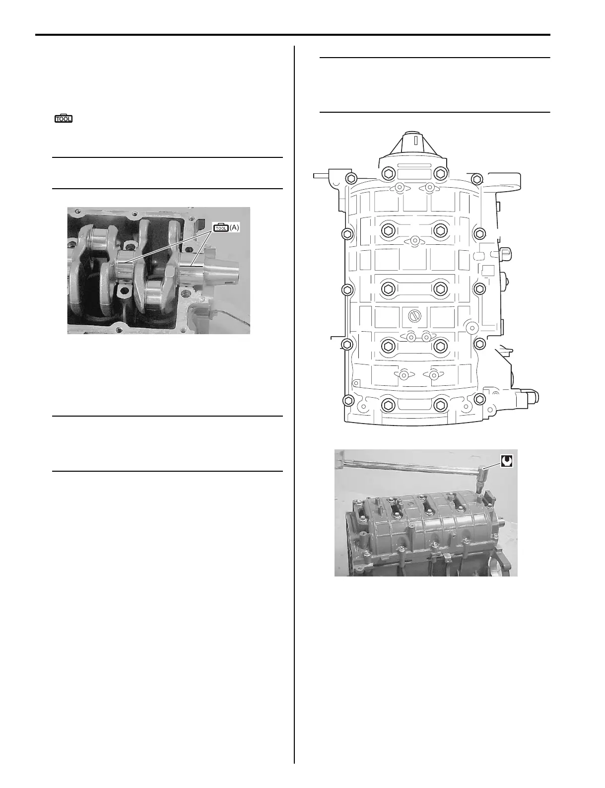
4) Place a piece of Plastigauge across full width of
bearing (parallel to crankshaft) on journal.
Do not place Plastigauge over oil hole.
Special tool
(A): 09900–22301 (Plastigauge (0.025 –
0.076 mm))
NOTE
Do not rotate crankshaft while Plastigauge is
installed.
5) Assemble crankcase to cylinder.
6) Apply engine oil to crankcase bolts.
Tighten crankcase bolts in three steps following the
order indicated below.
NOTE
Tighten 10 mm (0.394 in.) thread diameter
bolts first (following the order shown in
figure), then tighten 8 mm (0.315 in.) thread
diameter bolts.
Tightening torque
Crankcase inside bolt (10 mm thread diameter)
[1st step]: 11 N·m (1.1 kgf-m, 8.0 lbf-ft)
Crankcase inside bolt (10 mm thread diameter)
[2nd step]: 45 N·m (4.5 kgf-m, 32.5 lbf-ft)
Crankcase inside bolt (10 mm thread diameter)
[Final step]: 52 N·m (5.2 kgf-m, 37.5 lbf-ft)
Tightening torque
Crankcase outside bolt (8 mm thread diameter)
[1st step]: 6 N·m (0.6 kgf-m, 4.3 lbf-ft)
Crankcase outside bolt (8 mm thread diameter)
[2nd step]: 21 N·m (2.1 kgf-m, 15.0 lbf-ft)
Crankcase outside bolt (8 mm thread diameter)
[Final step]: 25 N·m (2.5 kgf-m, 18.1 lbf-ft)
NOTE
Crankcase must be torqued to specification
in order to assure proper compression of
plastigauge and accurate reading of
clearance.
7) Remove crankcase from cylinder.
I9J011140261-02
“9”
“6”
“2”
“4”
“8”
“5”
“9”
“6”
“2”
“4”
“8”
“5”
“1”
“1”
“3”
“3”
“7”
“7”
“10”
“10”
I9J011140018-03
I9J011140262-01