Power Trim and Tilt: 2B-15
Installation
Installation is reverse order of removal with special
attention to the following steps.
• Lower tilt rod to full down position.
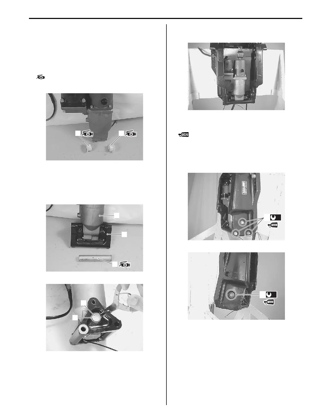
• Apply water resistant grease to the tilt cylinder lower
shaft and lower shaft bushings.
Install the lower shaft bushings (1) to PTT unit.
: Grease 99000–25161 (SUZUKI Water
Resistant Grease (250 g))
• Fit the PTT unit (2) to the lower clamp bracket (3) as
shown in figure and insert the tilt cylinder lower shaft
(4) through the lower clamp bracket and PTT unit.
Secure the tilt cylinder lower shaft with the snap rings
(5).
• Place the PTT unit (with lower clamp bracket) in
position between the clamp brackets.
• Tighten four lower clamp bracket bolts (6), pre-coated
with thread lock, to specified torque.
: Thread lock cement 99000–32050 (SUZUKI
Thread Lock 1342 (50 g))
Tightening torque
Lower clamp bracket bolt (a): 50 N·m (5.0 kgf-m,
36.0 lbf-ft)
1 1
I9J011220072-01
2
3
4
I9J011220073-01
5
4
I9J011220074-00
I9J011220075-01
(a)
6
I9J011220076-01
(a)
6
I9J011220077-01