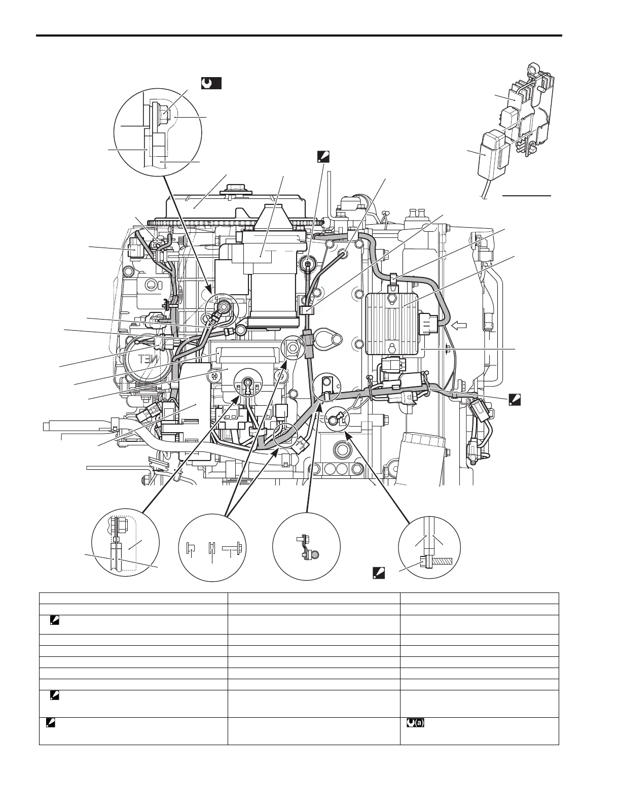
4A-4 Wire Routing:
View “A”
“A”
1
2
4
5
5
6
6
7
8
20
19
21
22
24
23
25
26
13
14
15
16
17
18
11
12
29
27
23
(a)
28
3
9
10
I9J011410003-03
1. Flywheel 11. Rectifier/Regulator GND lead wire 21. ECM
2. Starter motor 12. Main harness GND lead wire 22. IAT sensor
3. Oil pressure switch
: Cover the oil pressure switch with cap.
13. Bolt 23. Battery cable (+)
4. Ex. mani. temp. sensor 14. Cushion 24. Battery cable (–)
5. Rectifier/Regulator 15. Washer 25. IAC valve
6. Main harness capacitor 16. Cap 26. MAP sensor
7. Clamp 17. Main harness (Red) 27. Cap
8. Clamp 18. PTT relay lead wire (Red) 28. Nut
9. Clamp
: Bind the main harness, rectifier lead wire and
capacitor harness.
19. Fuse box 29. Main harness (Red)
10. Bolt
: Tighten bolt with harness GND lead and
Rectifier GND lead wire.
20. Electric parts holder : 8.6 N⋅m (0.86 kgf-m, 6.2 lbf-ft)