HYDROSTATIC POWER TRAIN
4203780 First Edition 5-61
5
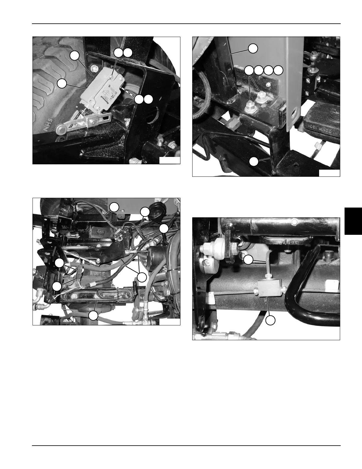
Figure 5-58
5. Remove two screws (4) and lock washers (5), and
remove front limit switch (6) and spacer (3).
Figure 5-59
6. Disconnect the reverse sensing switch wire harness
connector (8) from the wire harness connector (9).
7. Disconnect the brake pedal switch wire harness
connector (13) from the wire harness connector (12).
8. Cut cable ties (10) as needed.
9. Move the lift arm limit switch and harness (7) and
wire harnesses (11) aside.
Figure 5-60
10. Remove two nuts (15), lock washers (16), and
screws (17), and four flat washers (18) from console
support (14) and right side front lift arm support (19).
Figure 5-61
11. Disconnect the brake line (20) at tee fitting (21).
TN2044
6
4
5
4
5
3
TN2043
11
8
12
13
9
7
10
TN2050
18
15
16
17
14
19
TN2046
20
21

 Loading...


