STEERING
4203780 First Edition 7-25
7
Disassembly, Inspection, and Assembly
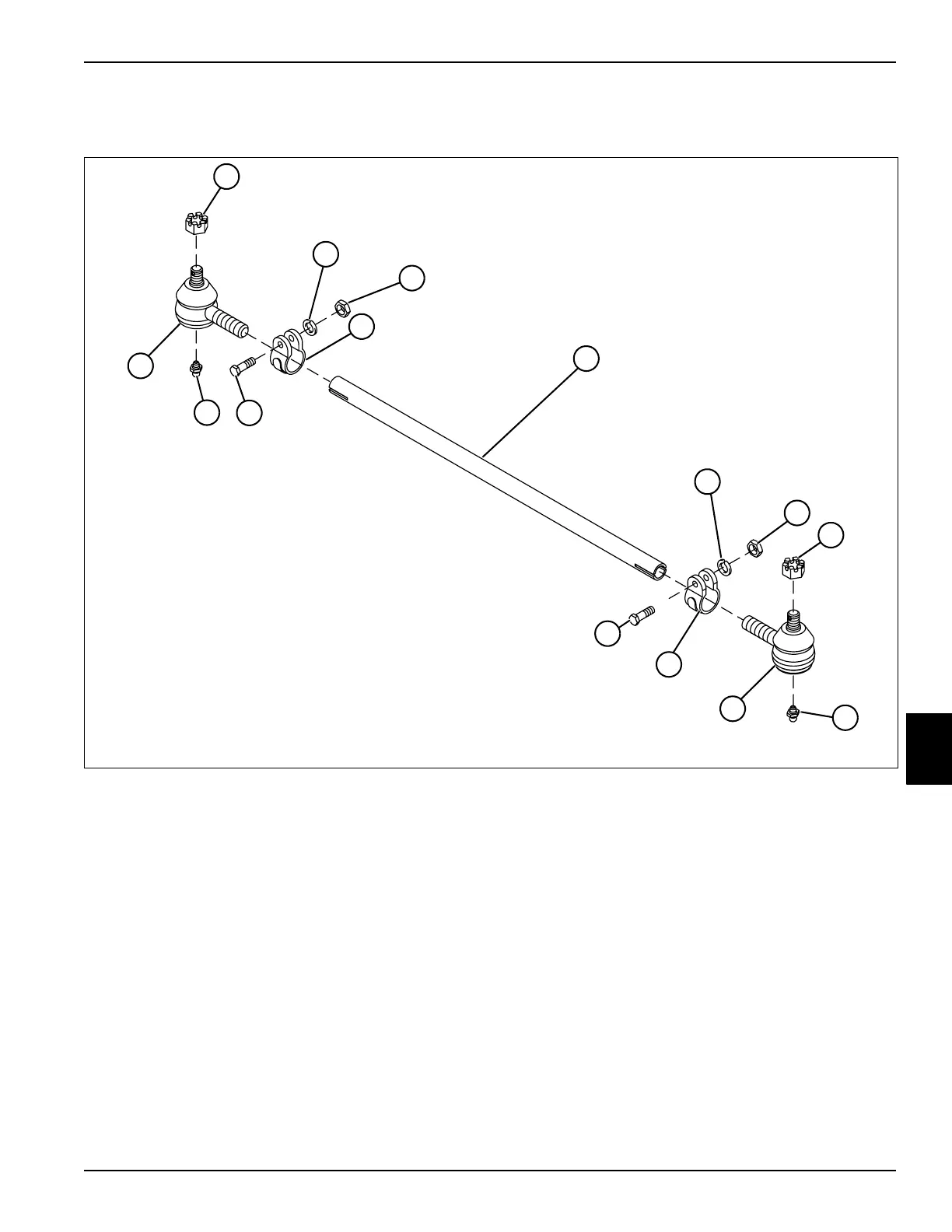
See Figure 7-41.
Figure 7-41
Disassembly Note
Record the number of turns required to remove ball joints
from tie rod.
Assembly Notes
• Assemble the tie rod assembly by reversing the order
of disassembly.
• Using information recorded during disassembly,
install ball joints into tie rod with the correct number
of turns.
• Apply grease to grease fittings (9).
1 Castle Nut 5 Tie Rod 9 Grease Fitting (2) 13 Hex-Head Bolt
2 Lock Washer 6 Lock Washer 10 Threaded Ball Joint, Left 14 Threaded Ball Joint, Right
3 Nut 7 Nut 11 Tie Rod Clamp
4 Tie Rod Clamp 8 Castle Nut 12 Hex-Head Bolt
TN1819
6
3
13
1
2
4
5
7
8
9
11
12
9
14
10

 Loading...


