ELECTRICAL
4203781 First Edition 4-75
4
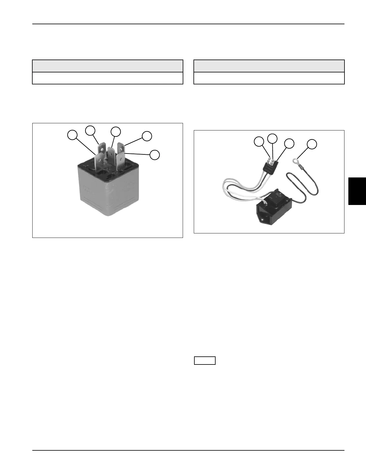
Relays Test
See Figure 4-38.
1. Park the mower safely. (See “Park Mower Safely” on
page 1-6.)
2. Remove relay. (See “Relays” on page 4-89.)
Figure 4-38
3. Connect one test lead to terminal (1).
4. Connect the other test lead to terminal (3) and check
for continuity.
Is continuity indicated?
YES Proceed to step 5.
NO The relay is faulty; replace the relay.
5. Connect one test lead to terminal (1).
6. Connect the other test lead to terminal (4).
7. Connect a 12-volt DC power source to terminals (2
and 5).
8. Check for continuity across terminals (4 and 1).
Is continuity indicated?
YES The relay is good.
NO The relay is faulty; replace the relay.
Time Delay Relay Test
See Figure 4-39.
1. Park the mower safely. (See “Park Mower Safely” on
page 1-6.)
2. Remove relay. (See “Time Delay Relay” on
page 4-90.)
Figure 4-39
3. Connect one test lead to terminal (1).
4. Connect the other test lead to terminal (2) and check
for continuity.
Is continuity indicated?
YES The relay is faulty; replace the relay.
NO Proceed to step 5.
5. Connect +12 volts to terminals (2 and 3), and
connect ground to terminal (4).
6. Measure voltage between terminals (1 and 4).
Is approximately 12 volts indicated?
YES The relay is good.
NO The relay is faulty; replace the relay.
NOTE
12 volts will remain indicated for approximately one
second after power is removed from relay.
Required Tools or Equipment
Digital Multimeter, Ohmmeter, or Continuity Tester
5
4
TN1531
1
2
3
Required Tools or Equipment
Digital Multimeter
4
2
5
3
TN2058
1
2
3
4

 Loading...

