ELECTRICAL
4203781 First Edition 4-109
4
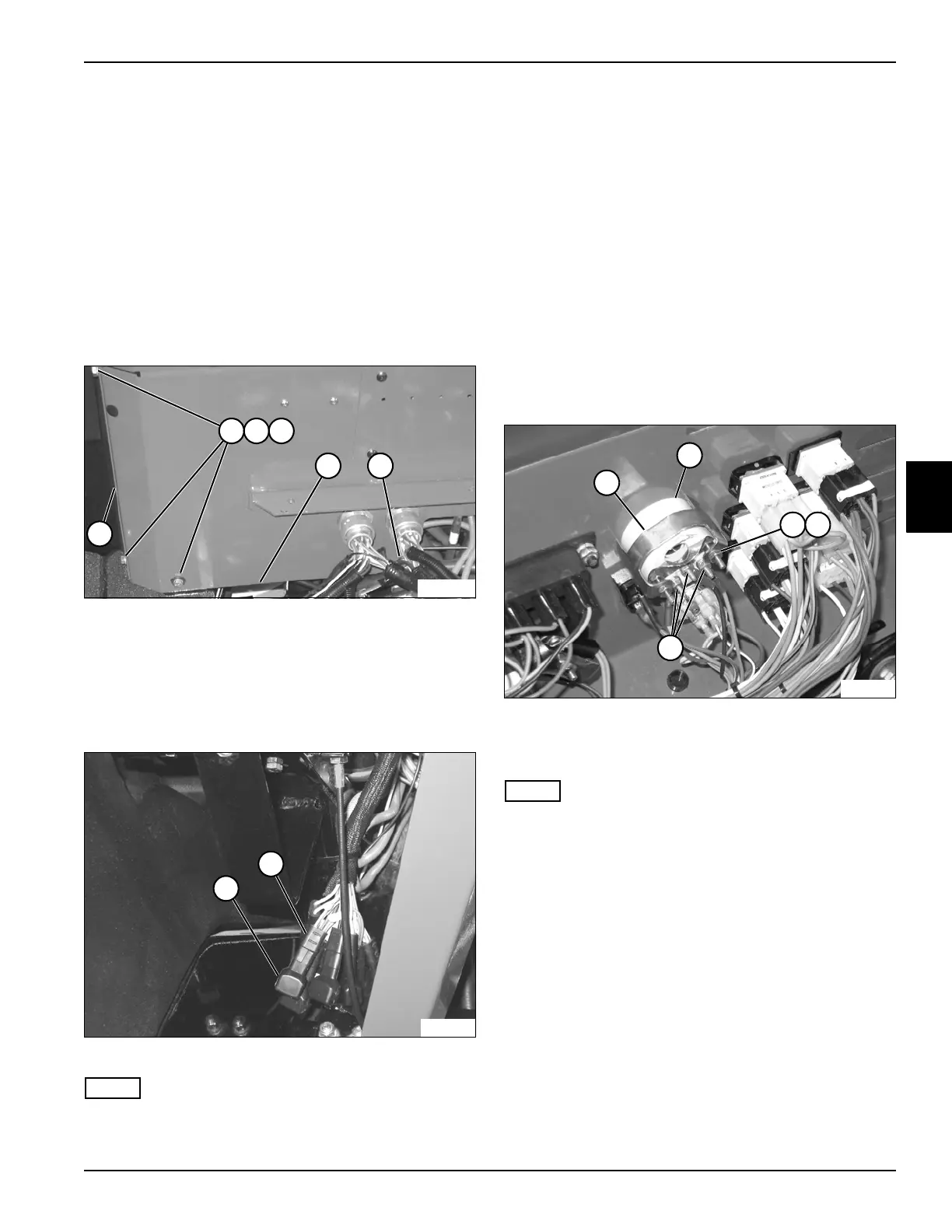
Diodes
Removal and Installation
See Figures 4-115 and 4-116.
1. Park the mower safely. (See “Park Mower Safely” on
page 1-6.)
2. Disconnect the negative (–) battery cable at the
battery.
3. Remove seat. (See “Seat and Seat Platform” on
page 9-10.)
4. Remove instrument panel. (See “Instrument Panel”
on page 4-87.)
Figure 4-115
5. Remove three screws (1), lock washers (2), and flat
washers (3).
6. Remove seal bracket (6).
7. Loosen screw (5) and move console wall (4) inward
to allow access to diode.
Figure 4-116
NOTE
Label all wires before disconnecting to ensure correct
installation.
8. Remove diode (6) from diode holder (7).
Installation Note
Install the diode by reversing the order of removal.
Engine Temperature Gauge
Removal and Installation
See Figure 4-117.
1. Park the mower safely. (See “Park Mower Safely” on
page 1-6.)
2. Disconnect the negative (–) battery cable at the
battery.
3. Remove instrument panel. (See “Instrument Panel”
on page 4-87.)
Figure 4-117
4. Remove two nuts (3), lock washers (4), and bracket
(1).
NOTE
Label all wires before disconnecting to ensure correct
installation.
5. Disconnect wire terminals (5).
6. Remove engine temperature gauge (2).
Installation Note
Install the engine temperature gauge by reversing the
order of removal.
TN2202
1 2 3
54
6
TN2256
6
7
1
TN2222
2
3
5
4

 Loading...

