4-108 4203781 First Edition
ELECTRICAL
4
Figure 4-112
6. Remove cruise control magnet (3) from bracket (4).
Installation Note
Install the cruise control magnet by reversing the order of
removal.
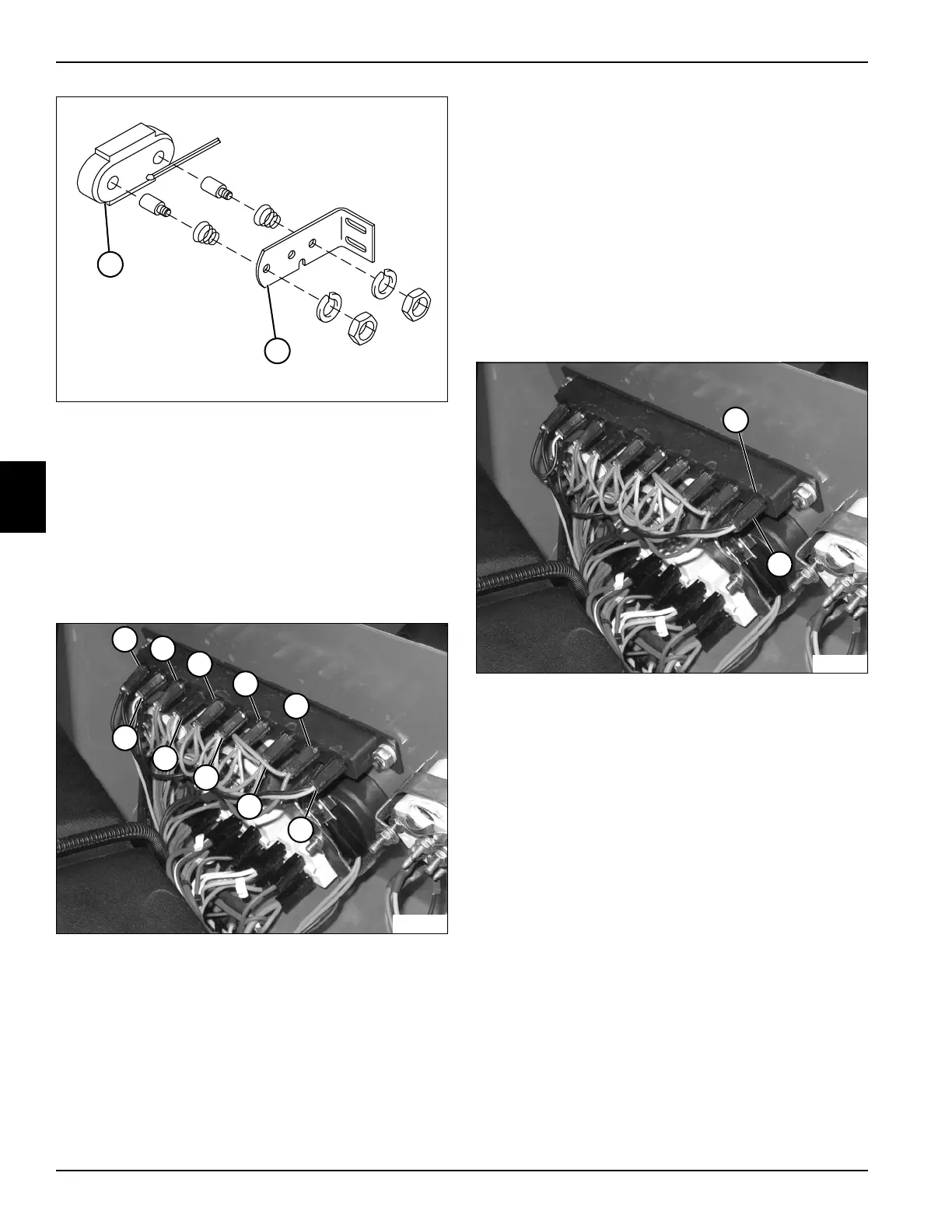
Indicator Lights
See Figure 4-113.
Figure 4-113
This procedure applies to the following indicator lights:
• Right Turn Indicator (1)
• Glow Plug Light (10)
• Air Filter Service Light (2)
• Return Filter Service Light (9)
• Hyd Oil Temp Light (3)
• Charge Filter Service Light (8)
• Low Charge Pressure Light (4)
• Engine Coolant Temp Light (7)
• Engine Oil Pressure Light (5)
• Left Turn Indicator (6)
Removal and Installation
See Figure 4-114.
1. Park the mower safely. (See “Park Mower Safely” on
page 1-6.)
2. Disconnect the negative (–) battery cable at the
battery.
3. Remove instrument panel. (See “Instrument Panel”
on page 4-87.)
Figure 4-114
4. Rotate indicator light holder (12) 1/8 turn
counterclockwise to disengage from socket (11).
5. Pull indicator light from indicator light holder.
Installation Note
Install the indicator light by reversing the order of
removal.
TN2042
4
3
TN2233
1
10
2
3
4
5
9
8
7
6
TN2233
12
11

 Loading...

