CUTTING UNITS
4203781 First Edition 8-29
8
Disassembly and Assembly
See Figure 8-22.
Figure 8-22
Disassembly Note
Inspect all moving parts for wear or damage. Replace as
necessary.
Assembly Notes
• Assemble fixed caster wheel in reverse order of
disassembly.
• Lubricate grease fitting with grease that meets or
exceeds NLGI Grade 2 LB specifications. Apply
grease with a manual grease gun and fill slowly until
grease begins to seep out. Do not use compressed
air gun.
• Set caster tire pressure to 20–25 psi (138–172 kPa).
Anti-Scalp Wheels
Removal and Installation
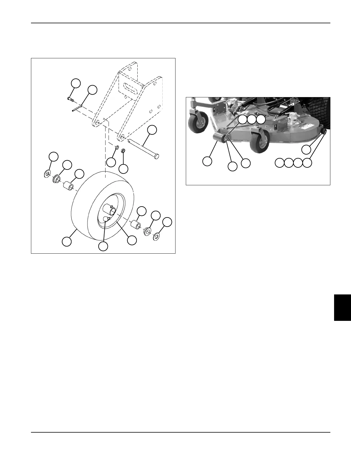
See Figure 8-23.
1. Park the mower safely. (See “Park Mower Safely” on
page 1-6.)
2. Raise and support cutting deck using jackstands.
Figure 8-23
3. Remove screw (1), lock washer (2), and nut (3).
4. Remove cotter pin (9).
5. Remove shaft (10) and anti-scalp wheel (11).
6. Remove screw (5), washer (6), spacer (7), and nut
(8) to remove anti-scalp wheel (4).
7. Inspect anti-scalp wheel for wear or damage.
Replace as necessary.
Installation Notes
• Inspect cotter pin for damage before installation.
• Install anti-scalp wheels by reversing the order of
removal.
1Screw 7Bushing (2)
2 Cotter Pin 8 Flat Washer (2)
3 Shaft 9 Wheel and Bearing
4 Lock Washer 10 Valve Stem
5Nut 11Tire
6 Bearing Roller (2)
TN1844
1
4
5
3
2
8
7
8
7
6
6
10
11
9
9
7
TN2139
4
1
10
11
2 3
568

 Loading...

