ELECTRICAL
4203781 First Edition 4-89
4
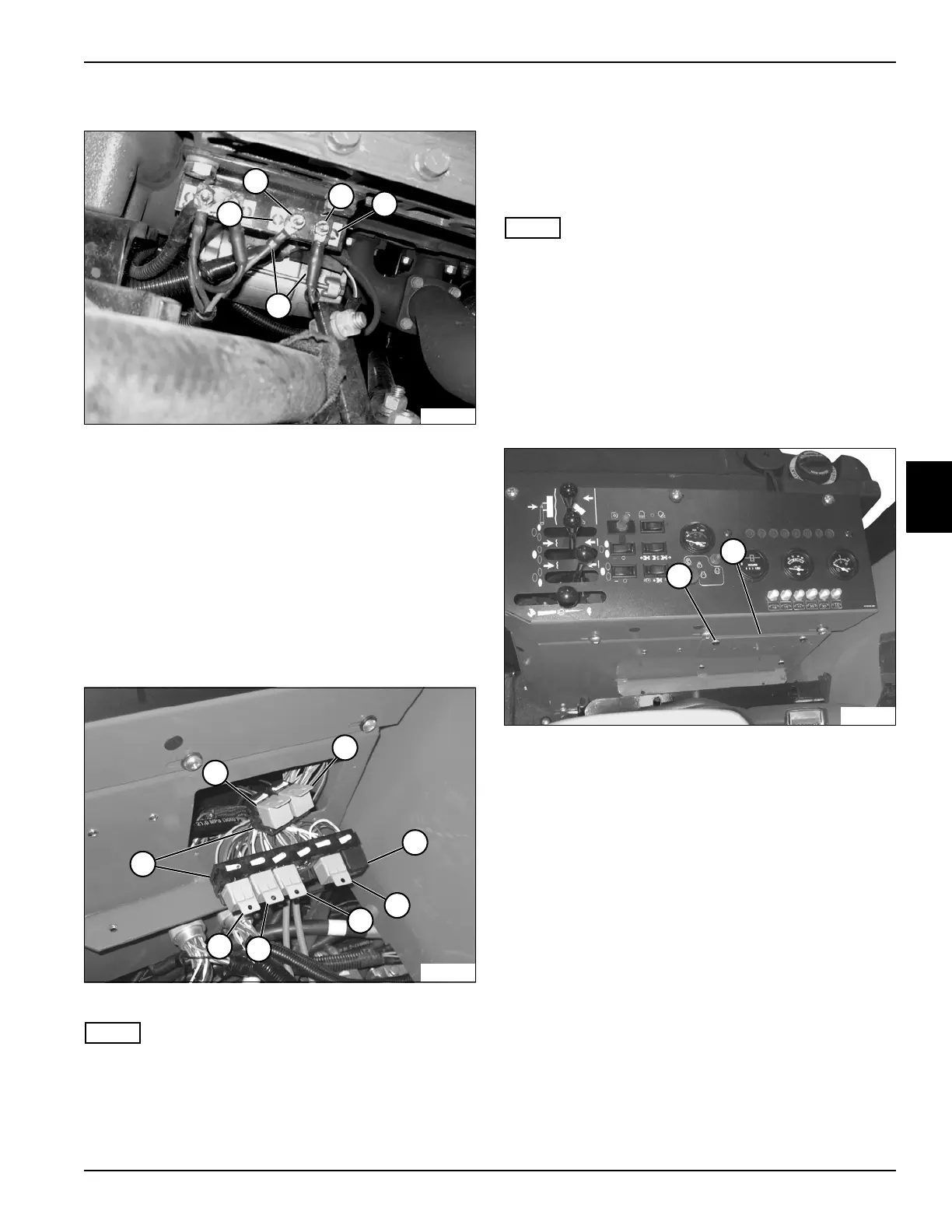
Main 50-Amp Thermal Circuit Breaker
Figure 4-64
6. Remove nuts (7 and 8) and disconnect wires (10).
7. Remove screws and nuts (6 and 9) and the thermal
breaker.
Installation Note
Install thermal circuit breakers by reversing the order of
removal.
Relays
See Figure 4-65.
Figure 4-65
NOTE
Seat removed for picture clarity.
This procedure applies to the following relays:
• Left Wing Relay (2)
• Right Wing Relay (1)
• Cruise Cancel Relay (3)
• Cruise Relay (4)
• Fuel Pull-In Relay (5)
• Horn Relay (6)
• Accessory Relay (7)
NOTE
For time delay relay, see “Time Delay Relay” on
page 4-90.
Removal and Installation
See Figures 4-66 and 4-67.
1. Park the mower safely. (See “Park Mower Safely” on
page 1-6.)
2. Disconnect the negative (–) battery cable at the
battery.
Figure 4-66
3. Remove four screws (9) and cover (10).
4. Pull relay straight out of the relay base (8).
Installation Note
Install the relay by reversing the order of removal.
7
TN1960
8
9
6
10
TN2260
2
4
6
7
1
3
5
8
TN2171
10
9

 Loading...

