9-10 4203781 First Edition
ACCESSORIES AND MISCELLANEOUS REPAIR
9
1. Park the mower safely. (See “Park Mower Safely” on
page 1-6.)
2. Remove two screws (2) from pedal arm (20).
3. Lift traction pedal (3) out and away from machine.
4. Remove screw (25), flat washer (24), lock nut (22),
and mow speed stop (23) from traction pedal.
5. Remove forward pedal grip (1) and reverse pedal grip
(4) from traction pedal.
6. Unplug reverse kick-out switch (17).
7. Remove two carriage bolts (5) and flange nuts (9).
8. Remove pivot screw (13), lock washer (12), and flat
washer (11).
9. Remove two nylon bearings (10) while separating
pedal arm (20) from pedal support bracket (8).
Inspect pedal arm pivot and nylon bearings for wear;
replace as necessary
10. Remove two screws (19), flat washers (18), lock
washers (15), and nuts (14) to remove reverse
kick-out switch (17) and switch shim (16) (if present)
from pedal support bracket (8).
Disassembly Note
Clean and inspect all moving parts, checking for wear,
damage, and binding parts.
Assembly Notes
•
• Assemble in reverse order of disassembly.
• Apply grease that meets or exceeds NLGI Grade 2
LB specifications to all pivot points.
• Do not overtighten lock nut (22). The mow speed
stop bracket (23) must be able to rotate after
assembly.
• Adjust mowing speed with tie studs (7).
• Check reverse kick-out switch (17) adjustment. (See
“Reverse Kick-Out Switch” on page 4-98.)
• Apply Loctite 272 (Red) to pivot screw (13) and
tighten to 9 lb-ft (12.2 N·m).
Seat and Seat Platform
Removal and Installation
See Figures 9-15 and 9-16.
1. Park the mower safely. (See “Park Mower Safely” on
page 1-6.)
2. Disconnect the negative (–) battery cable at the
battery.
3. Remove utility box. (See “Utility Box” on page 9-15.)
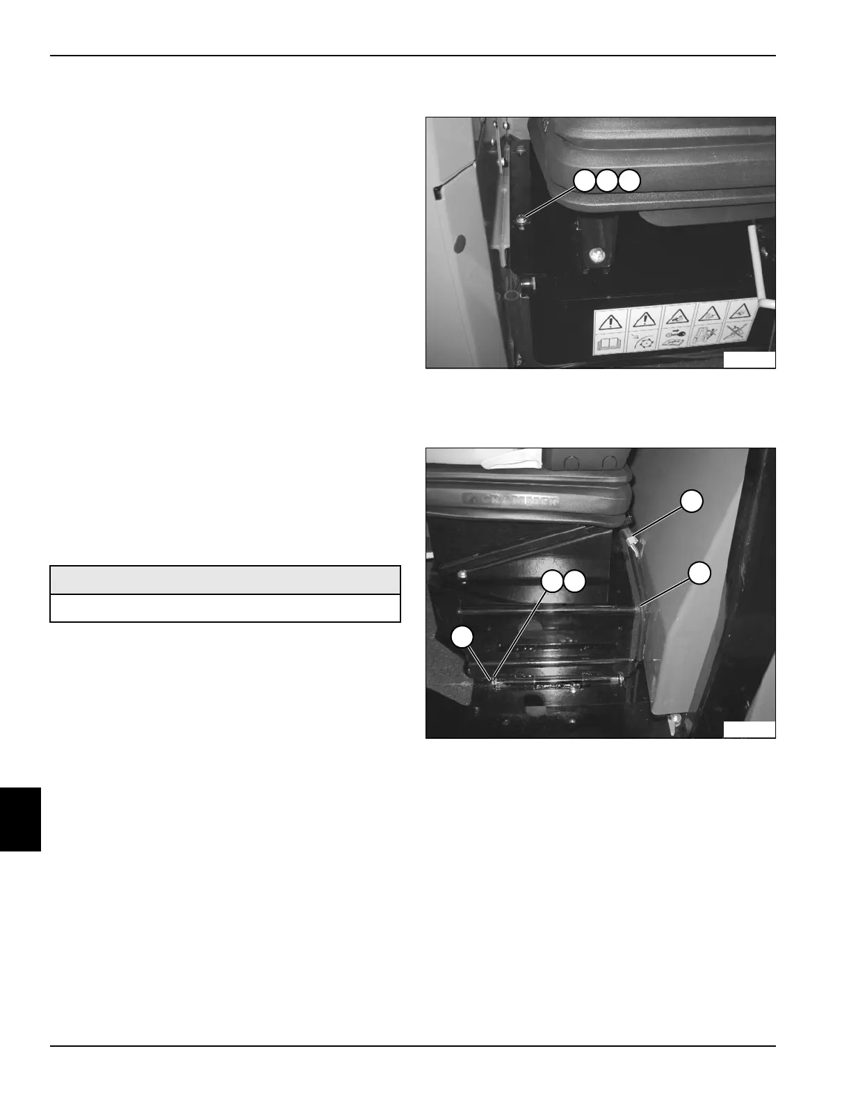
Figure 9-15
4. Remove two screws (1), lock washers (2), and flat
washers (3).
Figure 9-16
5. Tag and disconnect the operator’s seat switch wire
harness connector (5).
6. Remove two cotter pins (4), two flat washers (3), and
seat pivot rod (5).
7. Using a suitable lifting device, remove seat and seat
platform (2) from the machine.
Installation Notes
• Install the seat and seat platform by reversing the
order of removal.
• Carefully route and secure seat switch wire harness
to avoid damage from pinched wires.
Required Materials
Loctite
®
272 (Red)
TN2190
21 3
4
TN2189
3
5
2
1

 Loading...

