4-88 4203781 First Edition
ELECTRICAL
4
Installation Notes
• Anti-seize must be applied to screw threads when
installing instrument panel.
• Install the instrument panel by reversing the order of
removal.
Circuit Breakers
Removal and Installation
See Figures 4-61 and 4-62.
1. Park the mower safely. (See “Park Mower Safely” on
page 1-6.)
2. Disconnect the negative (–) battery cable at the
battery.
3. Remove instrument panel. (See “Instrument Panel”
on page 4-87.)
Figure 4-61
4. Remove nut (1).
Figure 4-62
NOTE
Label all wires before disconnecting to ensure correct
installation.
5. Disconnect wire connectors (2 and 4).
6. Remove circuit breaker (3).
Installation Note
Install the circuit breaker by reversing the order of
removal.
Thermal Circuit Breakers
Removal and Installation
See Figures 4-63 and 4-64.
1. Park the mower safely. (See “Park Mower Safely” on
page 1-6.)
2. Raise the hood.
3. Disconnect the negative (–) battery cable at the
battery.
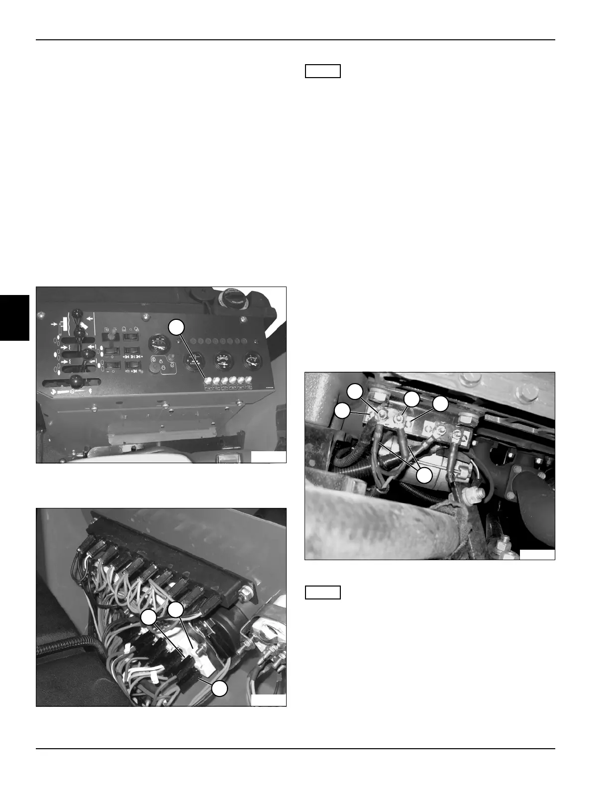
Glow Plug and Work Lights 50-Amp Thermal Circuit
Breaker
Figure 4-63
NOTE
Label all wires before disconnecting to ensure correct
installation.
4. Remove nuts (2 and 3) and disconnect wires (5).
5. Remove screws and nuts (1 and 4) and the thermal
breaker.
TN2171
1
TN2233
3
2
4
2
TN1960
3
4
1
5

 Loading...

