4-94 4203781 First Edition
ELECTRICAL
4
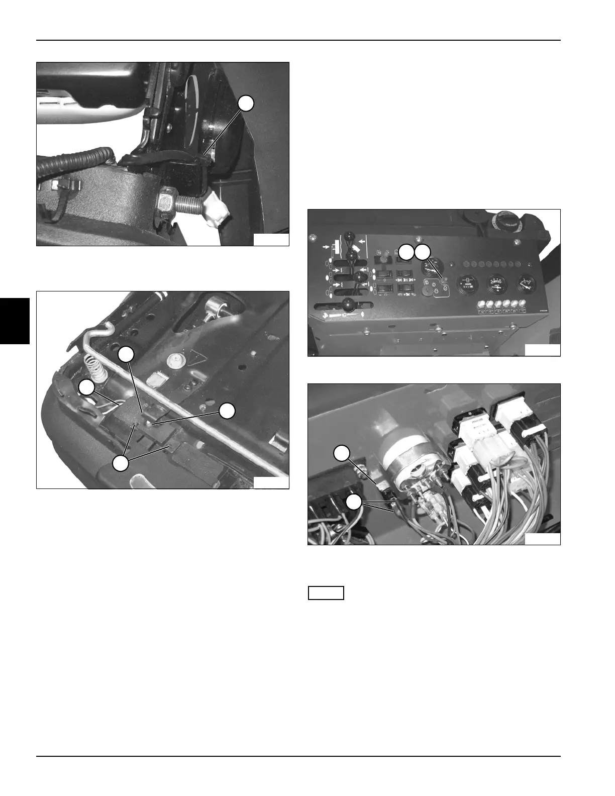
Figure 4-77
10. Cut cable tie (9).
Figure 4-78
11. Disengage switch cover tabs (12) and remove switch
cover (13).
12. Raise end of switch actuator (10) and remove seat
switch (11).
Installation Notes
• Install the seat switch by reversing the order of
removal.
• Use new cable ties to secure wire harness and wire
connectors.
Glow Plug Switch
Removal and Installation
See Figures 4-79 and 4-80.
1. Park the mower safely. (See “Park Mower Safely” on
page 1-6.)
2. Disconnect the negative (–) battery cable at the
battery.
3. Remove instrument panel. (See “Instrument Panel”
on page 4-87.)
Figure 4-79
Figure 4-80
4. Remove boot (1) and two retaining nuts (2).
NOTE
Label all wires before disconnecting to ensure correct
installation.
5. Disconnect wire connectors (4).
6. Remove glow plug switch (3).
Installation Note
Install the glow plug switch by reversing the order of
removal.
TN2272
9
TN2273
12
13
11
10
TN2171
1 2
TN2222
3
4

 Loading...

