CUTTING UNITS
4203781 First Edition 8-27
8
Disassembly Note
Inspect all moving parts for wear or damage. Replace as
necessary.
Assembly Notes
• Assemble wing deck lift arm in reverse order of
disassembly.
• Lubricate grease fittings with grease that meets or
exceeds NLGI Grade 2 LB specifications. Apply
grease with a manual grease gun and fill slowly until
grease begins to seep out. Do not use compressed
air gun.
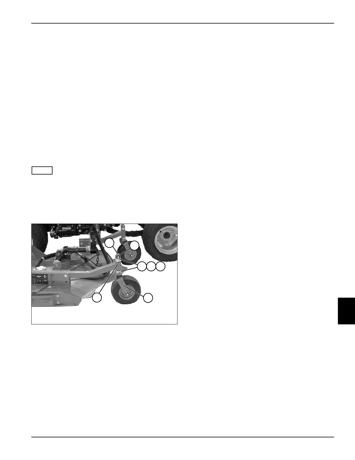
Swivel Caster Wheels
Removal and Installation
See Figure 8-19.
NOTE
Note position and order of flat washers and height-of-cut
spacers for proper installation.
1. Park the mower safely. (See “Park Mower Safely” on
page 1-6.)
2. Raise and support cutting deck using jackstands.
Figure 8-19
3. Support caster wheel assembly (6).
4. Remove lock pin (2).
5. Slide the top flat washers (3), caster wheel spacer
(4), and height-of-cut spacers (5) off yoke (1).
6. Remove caster wheel assembly (6), bottom
height-of-cut spacers (5), and caster wheel spacer
(4), from bottom of caster arm (7).
7. Inspect yoke (1) along with the flat washers (3),
caster wheel spacers (4), and height-of-cut spacers
(5) for wear or damage. Replace as necessary.
8. Inspect caster arm (7) for wear or damage, and
replace as necessary.
Installation Notes
• Install the swivel caster wheels by reversing the order
of removal.
• Lubricate grease fittings with grease that meets or
exceeds NLGI Grade 2 LB specifications. Apply
grease with a manual grease gun and fill slowly until
grease begins to seep out. Do not use compressed
air gun.
TN2138
6
7
1
2
4 53

 Loading...

