9-16 4203781 First Edition
ACCESSORIES AND MISCELLANEOUS REPAIR
9
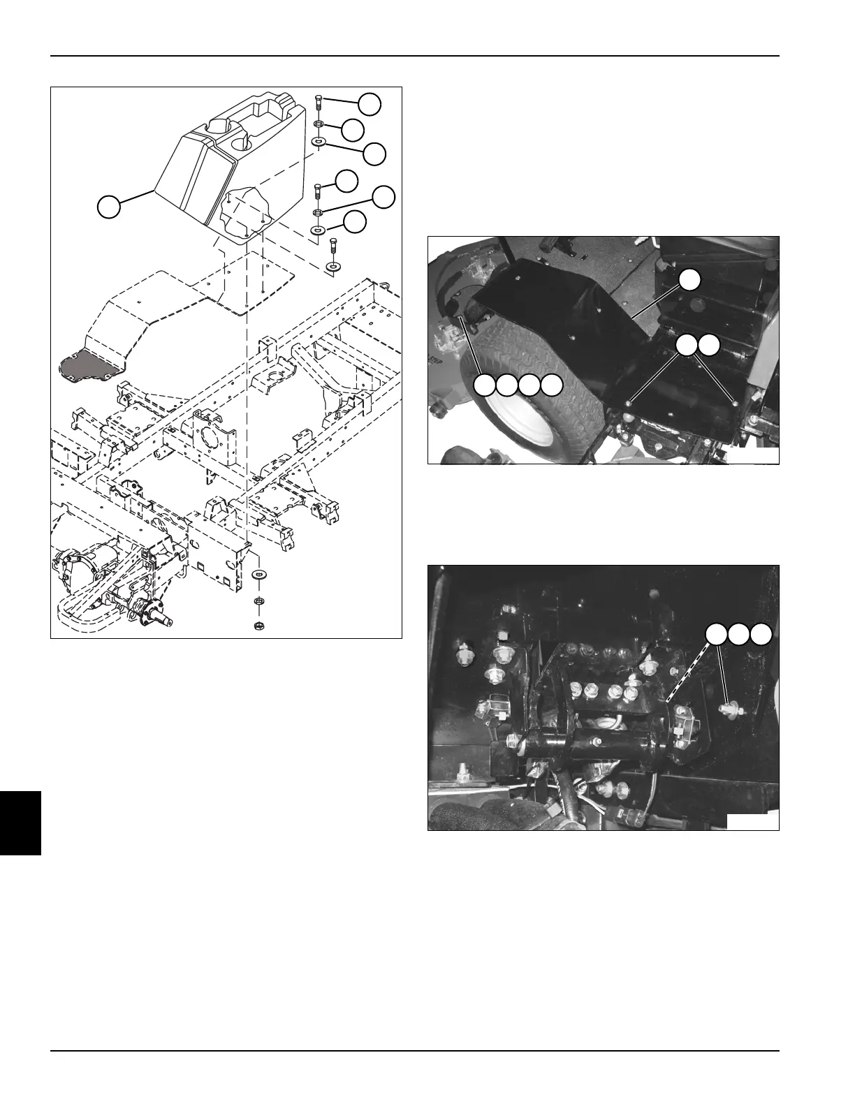
Figure 9-29
3. Support the utility box (1) and remove four screws
(4), lock washers (5), and flat washers (6).
4. Remove utility box from the machine.
Installation Note
Install the utility box by reversing the order of removal.
Left Fender
Removal and Installation
See Figures 9-30 and 9-31.
1. Park the mower safely. (See “Park Mower Safely” on
page 1-6.)
2. Remove utility box. (See “Utility Box” on page 9-15.)
Figure 9-30
3. Remove three nuts (4), lock washers (5), flat washers
(6), and screws (7).
4. Remove two flange nuts (2) and screws (3).
Figure 9-31
5. Remove nuts (8), lock washers (9), and carriage
bolts (10).
6. Remove left fender (1).
Installation Note
Install the left fender by reversing the order of removal.
1
TN2118
4
5
6
4
5
6
4
TN2207
2 3
1
5 6 7
TN2198
9 108

 Loading...

