HYDRAULICS
4203781 First Edition 6-67
6
Assembly Notes
NOTICE
• Assemble the deck valve by reversing the order of
disassembly.
• Lubricate all O-rings prior to assembly.
• Tighten relief valve (2) to 33–37 lb-ft (44.7–
50.2 N·m).
• Tighten relief valve (5) to 24–26 lb-ft (32.5–
35.3 N·m).
• Tighten solenoid valve to 24–26 lb–ft (32.5–
35.3 N·m).
• Tighten solenoid valve nut to 5–7 lb-ft (6.8–9.5 N·m).
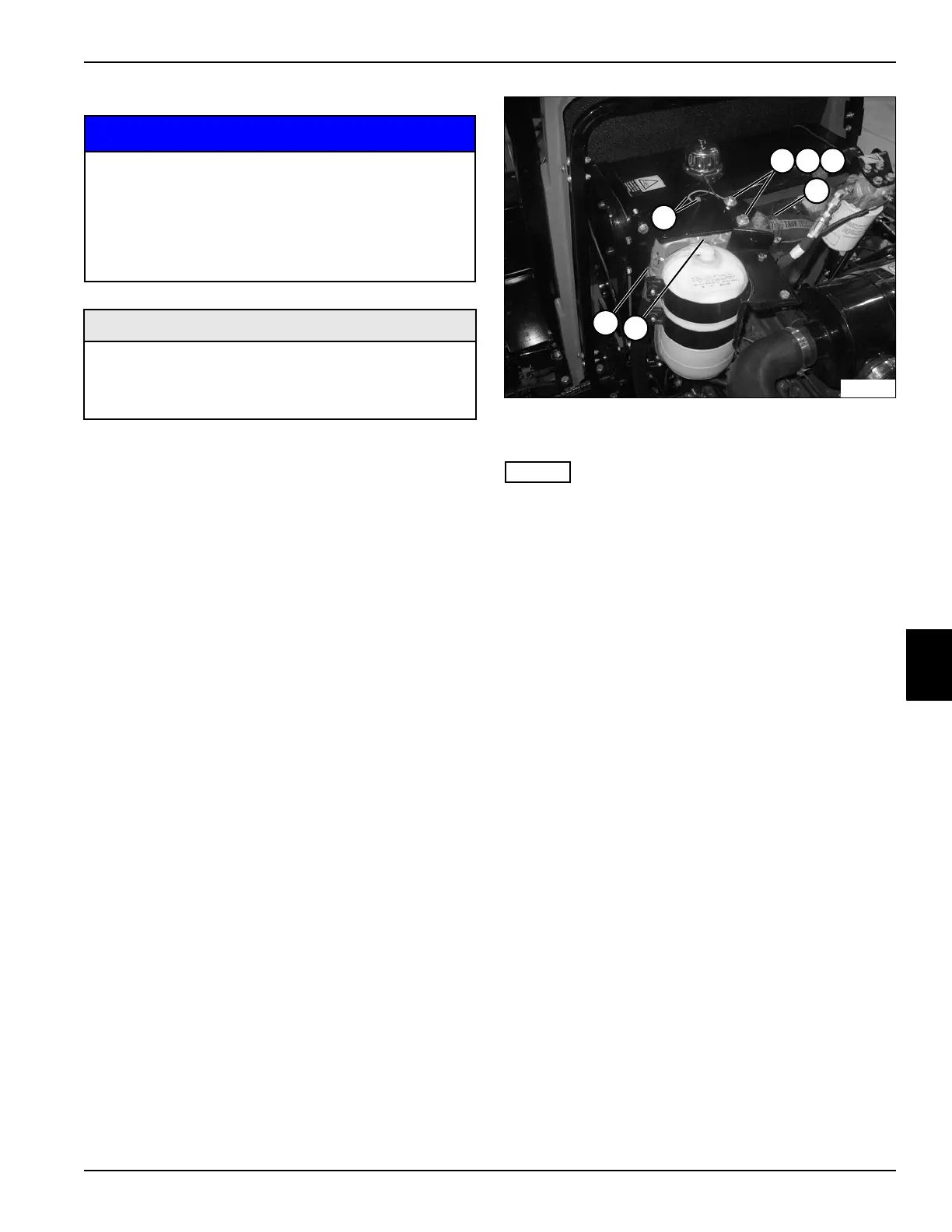
Hydraulic Oil Return Filter
Removal and Installation
See Figure 6-72.
1. Park the mower safely. (See “Park Mower Safely” on
page 1-6.)
2. Raise engine hood.
3. Drain hydraulic oil tank. (See “Hydraulic Oil Tank—
Drain Procedure” on page 6-58.)
Figure 6-72
4. Disconnect electrical connectors (1).
NOTES
• Label all hydraulic hoses to aid in installation.
• Close all openings with caps or plugs to prevent
contamination.
5. Disconnect hydraulic hoses (5 and 7).
6. Support the oil filter assembly (6).
7. Remove two screws (2), lock washers (3), and flat
washers (4).
8. Remove oil filter assembly (6).
Installation Notes
• Install oil filter assembly by reversing the order of
removal.
• Replace hydraulic oil filter.
• Refill hydraulic tank. (Refer to “Safety, Operation, and
Maintenance Manual” for oil specifications.)
• Start engine. Check hydraulic system for leaks.
Repair as necessary.
• Check hydraulic oil level and add if necessary.
Charge Pressure Filter
Removal and Installation
See Figure 6-73.
1. Park the mower safely. (See “Park Mower Safely” on
page 1-6.)
2. Raise engine hood.
3. Drain hydraulic oil tank. (See “Hydraulic Oil Tank—
Drain Procedure” on page 6-58.)
It is important that all component parts are
absolutely clean, as contamination can result in
serious damage and/or improper operation.
Never use shop towels or rags to dry parts after
cleaning, as lint may clog passages. Dry parts
using compressed air.
Required Materials
• Seal Kit, Solenoid Valve (Jacobsen P/N 5003579)
• Seal Kit, Relief Valve (Jacobsen P/N 5003554)
• Seal Kit, Relief Valve (Jacobsen P/N 5003579)
5
6
7
TN2293
1
2
3 42

 Loading...

