4-90 4203781 First Edition
ELECTRICAL
4
Time Delay Relay
Removal and Installation
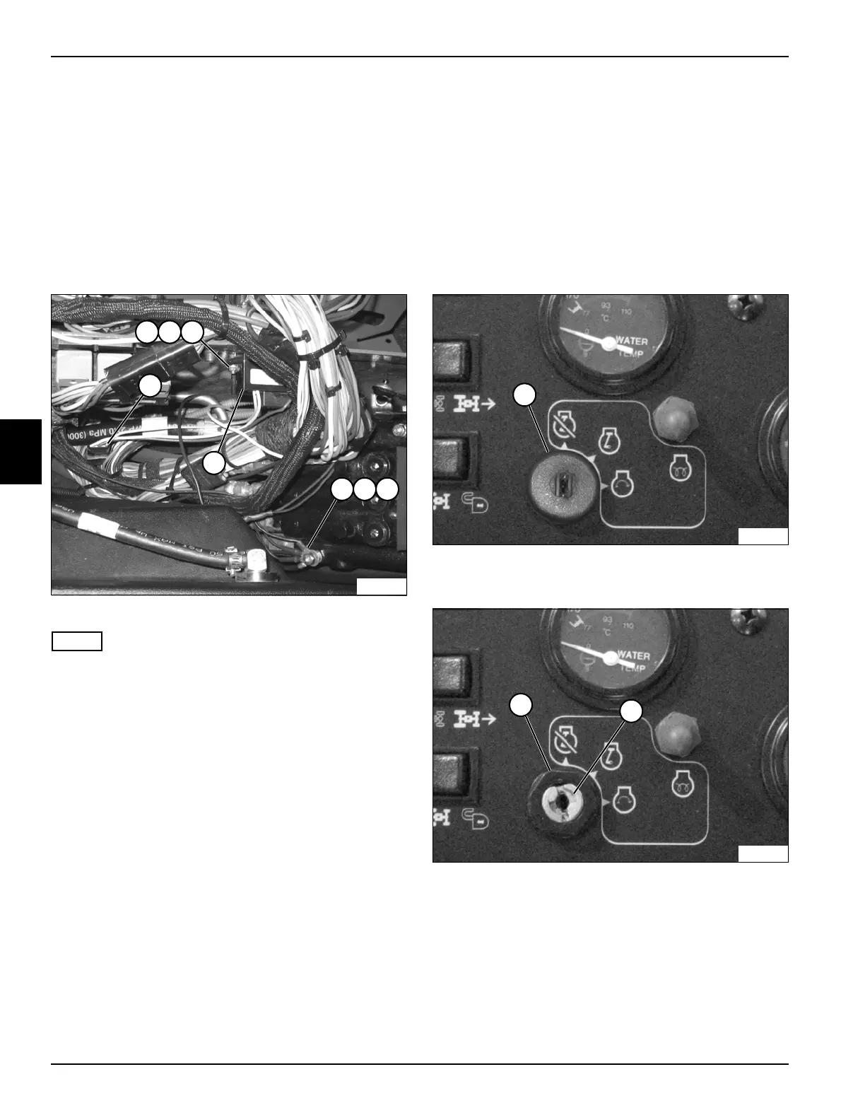
See Figure 4-67.
1. Park the mower safely. (See “Park Mower Safely” on
page 1-6.)
2. Disconnect the negative (–) battery cable at the
battery.
3. Remove instrument panel. (See “Instrument Panel”
on page 4-87.)
Figure 4-67
NOTE
Label all wires before disconnecting to ensure correct
installation.
4. Disconnect wire connector (4).
5. Remove nut (6), lock washer (7), and ground wire
terminal (8).
6. Remove two nuts (1), lock washers (2), and screws
(3).
7. Remove time delay relay (5).
Installation Note
Install the time delay relay by reversing the order of
removal.
Key Switch
Removal and Installation
See Figures 4-68 through 4-70.
1. Park the mower safely. (See “Park Mower Safely” on
page 1-6.)
2. Disconnect the negative (–) battery cable at the
battery.
3. Remove instrument panel. (See “Instrument Panel”
on page 4-87.)
Figure 4-68
4. Remove key switch cover (1).
Figure 4-69
5. Remove retaining nut (2) from the key switch (3).
TN2254
1
5
4
2 3
6 7 8
TN2169
1
2
TN2170
3

 Loading...

