4-92 4203781 First Edition
ELECTRICAL
4
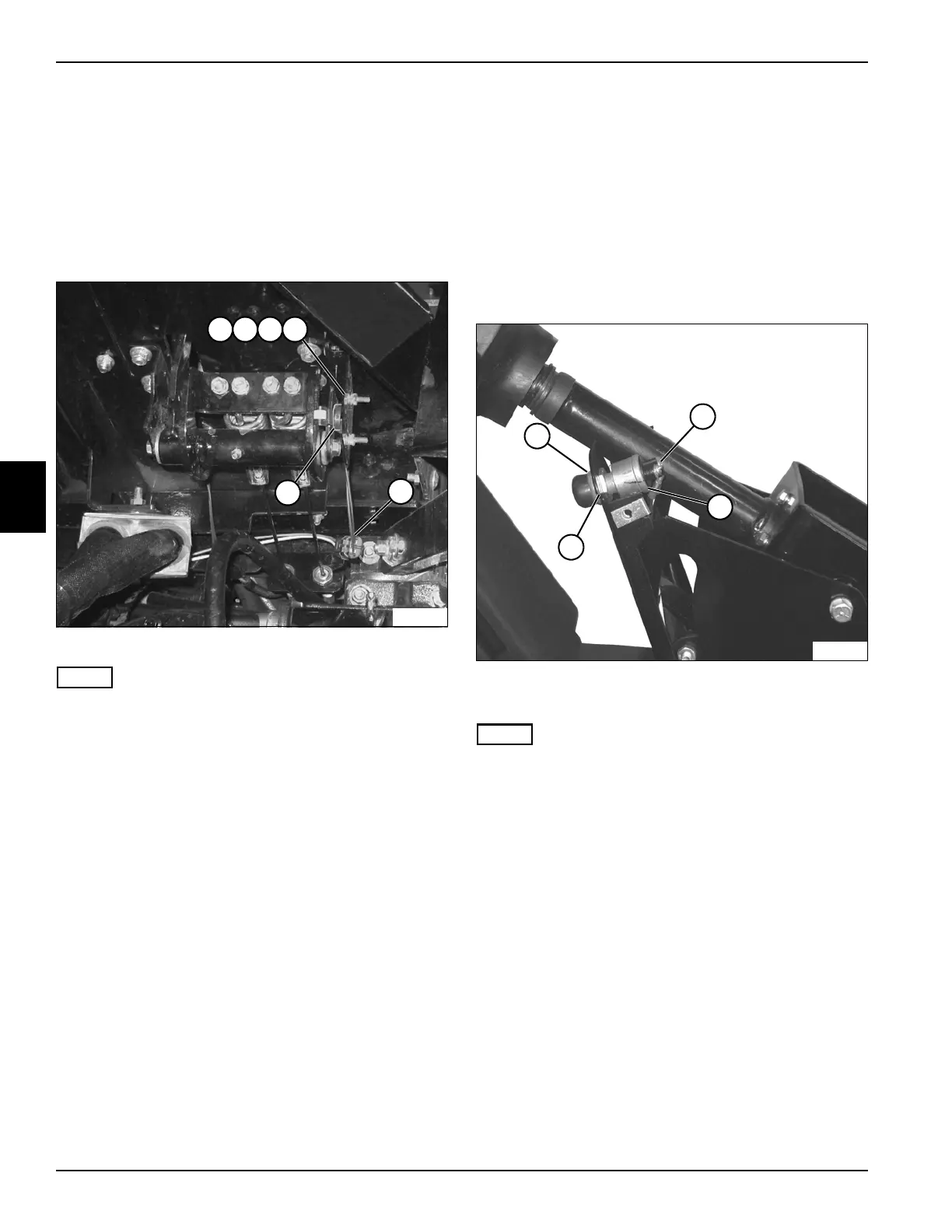
Brake Pedal Switch
Removal and Installation
See Figure 4-72.
1. Park the mower safely. (See “Park Mower Safely” on
page 1-6.)
2. Disconnect the negative (–) battery cable at the
battery.
Figure 4-72
NOTE
Label all wires before disconnecting to ensure correct
installation.
3. Disconnect wire connector (6).
4. Remove two nuts (1), lock washers (2), flat washers
(3), and screws (4).
5. Remove brake pedal switch (5).
Installation Notes
• Install the brake pedal switch by reversing the order
of removal.
• Position the brake pedal switch so contacts are
closed with the brake pedal disengaged, and open as
soon as the brake pedal is pressed.
Horn/Test Switch
Removal and Installation
See Figure 4-73.
1. Park the mower safely. (See “Park Mower Safely” on
page 1-6.)
2. Disconnect the battery negative (–) cable at the
battery.
3. Remove the steering tower cover. (See “Steering
Tower Cover” on page 7-8.)
Figure 4-73
4. Remove bezel nut (1).
NOTE
Label all wires before disconnecting to ensure correct
installation.
5. Disconnect wire terminals (2).
6. Remove horn/test switch (3).
Installation Notes
• Adjust jam nut (4) for proper switch height, if
necessary.
• Install horn switch by reversing the order of removal.
TN2180
6
5
1 2 3 4
TN2183
2
3
4
1

 Loading...

