5-30 4203781 First Edition
HYDROSTATIC POWER TRAIN
5
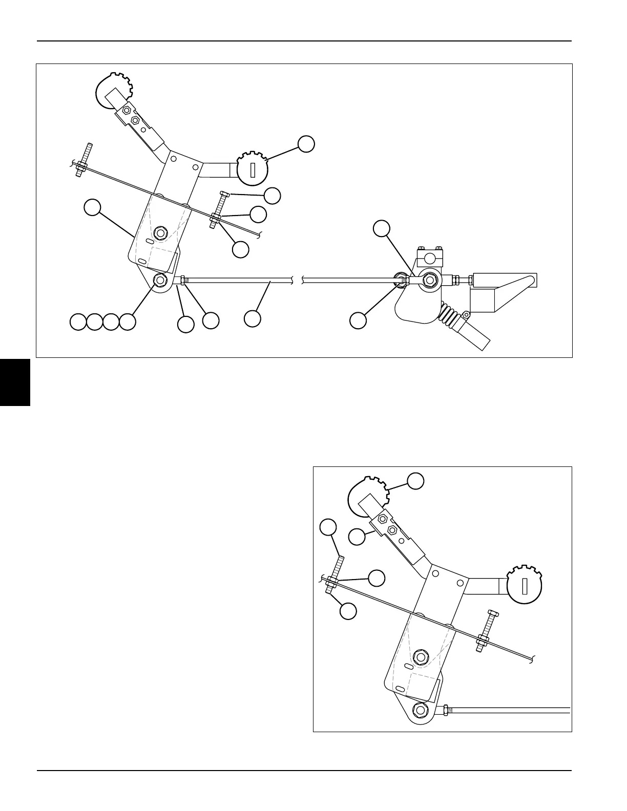
Figure 5-16
1. Loosen lock nuts (12).
2. Remove nut (15), lock washer (16), two flat washers
(17), and screw (18) from ball joint (14), and
disconnect the ball joint from the throttle pedal lever
(7).
3. Adjust the overall length of the traction pedal rod
(13), by turning the ball joints (14 and 11), in to
shorten or out to lengthen, as needed. If the pedal
touches the rear stop stud (9) before reaching the
required length of the traction pedal rod (13), adjust
the stop stud position.
4. Loosen nuts (10).
5. Adjust (turn) the rear stop stud (9) in (clockwise).
6. Move the traction pedal (8) to the required reverse
position and hold.
7. Adjust (turn) the rear stop stud (9) counterclockwise,
until it touches the traction pedal (8), then one
additional turn.
8. Tighten nuts (10).
9. Tighten lock nuts (12).
10. Connect the traction pedal rod ball joint (14) to the
throttle pedal lever (7) using nut (15), lock washer
(16), two flat washers (17), and screw (18).
11. Start the engine and check the reverse speed.
12. Stop the engine.
13. Repeat steps 1 through 12 as needed until the
correct adjustment is obtained.
14. When the desired reverse speed adjustment is
obtained, proceed to “Forward” adjustment.
Forward
The forward limit is adjusted by changing the height of
the front stop stud under the traction pedal.
Figure 5-17
TN2342
TN2342
13
12 12
15161718
14
7
11
9
8
10
10
TN2349
TN2349
22
21
19
22
20

 Loading...

