6-38 4203781 First Edition
HYDRAULICS
6
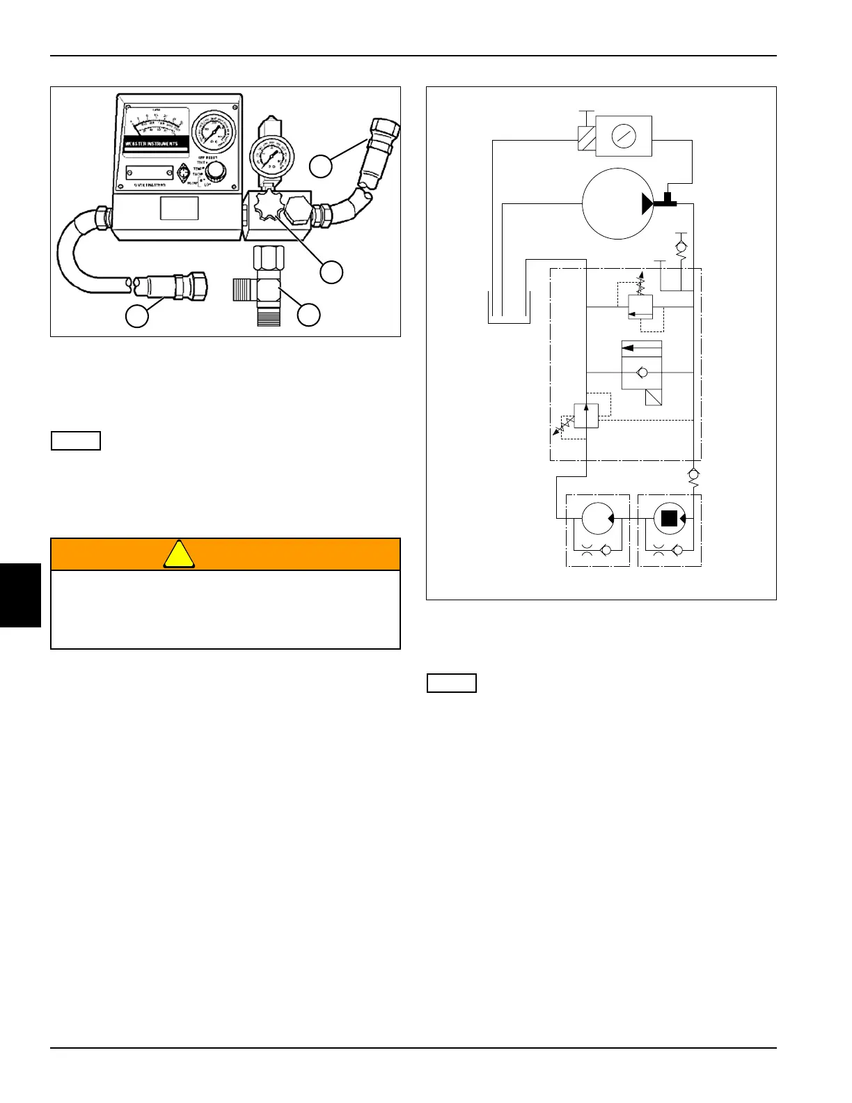
Figure 6-31
4. Install tee fitting (5) to fitting (1).
5. Connect test hose (6) of flow meter inlet and hose (2)
to tee fitting (5).
NOTE
Make sure hose end is under oil level in hydraulic tank to
prevent aeration of oil.
6. Secure flow meter outlet hose (3) to the hydraulic
tank fillneck.
!
WARNING
7. Install suitable blocking device or tool in right wing
outside cutting unit motor, preventing right wing
cutting unit motor from turning.
8. Open flow meter valve (4) completely.
Figure 6-32: Right Wing Cutting Unit Circuit Test—
Outside Cutting Unit Motor Blocked
9. Bypass seat switch and set park brake.
NOTE
Verify engine rpm is within specification (2800 rpm ± 50)
to ensure accurate hydraulic test results.
10. Start engine and run at full throttle (2800 rpm ± 50).
11. Use the flow meter to warm the hydraulic oil. Turn the
flow meter valve (4) until a reading of 1500 psi (103
bar) or one half of the relief valve rating is reached.
Warm oil to 120–150° F (49–65° C); open valve fully
after operating temperature is reached.
12. Enable wing mower deck switch and engage PTO
switch.
13. Read and record the right wing cutting unit circuit no
load flow.
14. Slowly close flow meter valve (4) until pressure
reaches 2250 psi (155 bar). Read and record the
right wing cutting unit circuit loaded flow.
15. Open flow meter valve (4), disengage switches, and
stop engine.
Safely block cutting unit from rotating using a
suitable device or tool. Failure to follow
appropriate safety precaution may result in death
or serious injury.
5
6
TN1363
4
3
TN2250

 Loading...

