ELECTRICAL
673831-Rev A 4-57
4
Light Switch Test
See Figure 4-29.
1. Park the mower safely. (See “Park Mower Safely” on
page 1-6.)
2. Remove the optional light switch. (See “Rocker
Switches” on page 4-64.)
Figure 4-29
3. Place the switch in the OFF position.
4. Connect test leads to the switch terminals (2 and 3).
5. Check for continuity.
Is continuity indicated?
YES The switch is faulty; replace the switch.
NO Proceed to step 6.
6. Place the switch in the ON position.
7. Check for continuity.
Is continuity indicated?
YES The switch is good.
NO The switch is faulty; replace the switch.
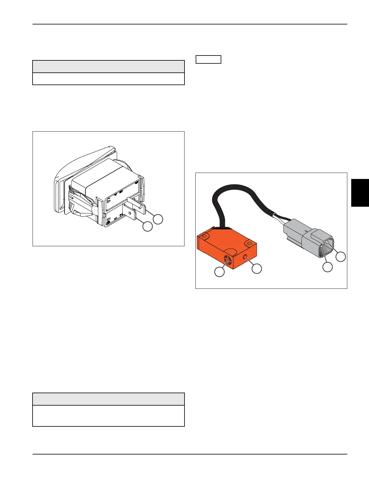
Proximity Switches Test
See Figure 4-30.
1. Park the mower safely. (See “Park Mower Safely” on
page 1-6.)
This procedure applies to the following micro switches:
• Neutral Switch
• Forward Switch
• Lift Proximity Switch
• The proximity switch is a solid state switch and will
have approximately a 2 to 3 volt drop across the
switch when activated,
• The switch must be tested with the switch plugged
into the main harness and the key switch in the RUN
position.
• The switch may have to be removed from the
mounting bracket to properly test the switch.
Figure 4-30
2. Confirm that 12-volts DC is present at terminal (1)
(white wire) of the proximity switch.
With no metal object in front of switch sensing
target (3), does the light (4) come on?
YES The switch is faulty; replace the switch.
NO Proceed to step 3.
3. Place a piece of steel approximately 1/8 in. (3 mm) in
front of sensor target (3).
Does the light (4) come on?
YES The switch is good.
NO The switch is faulty; replace the switch.
Required Tools or Equipment
Digital Multimeter, Ohmmeter, or Continuity Tester
Required Tools or Equipment
• Digital Multimeter, Ohmmeter, or Continuity Tester
• Small piece of steel
2
3

 Loading...

