8-36 673831-Rev A
CUTTING UNITS
8
Front Roller
Removal and Installation
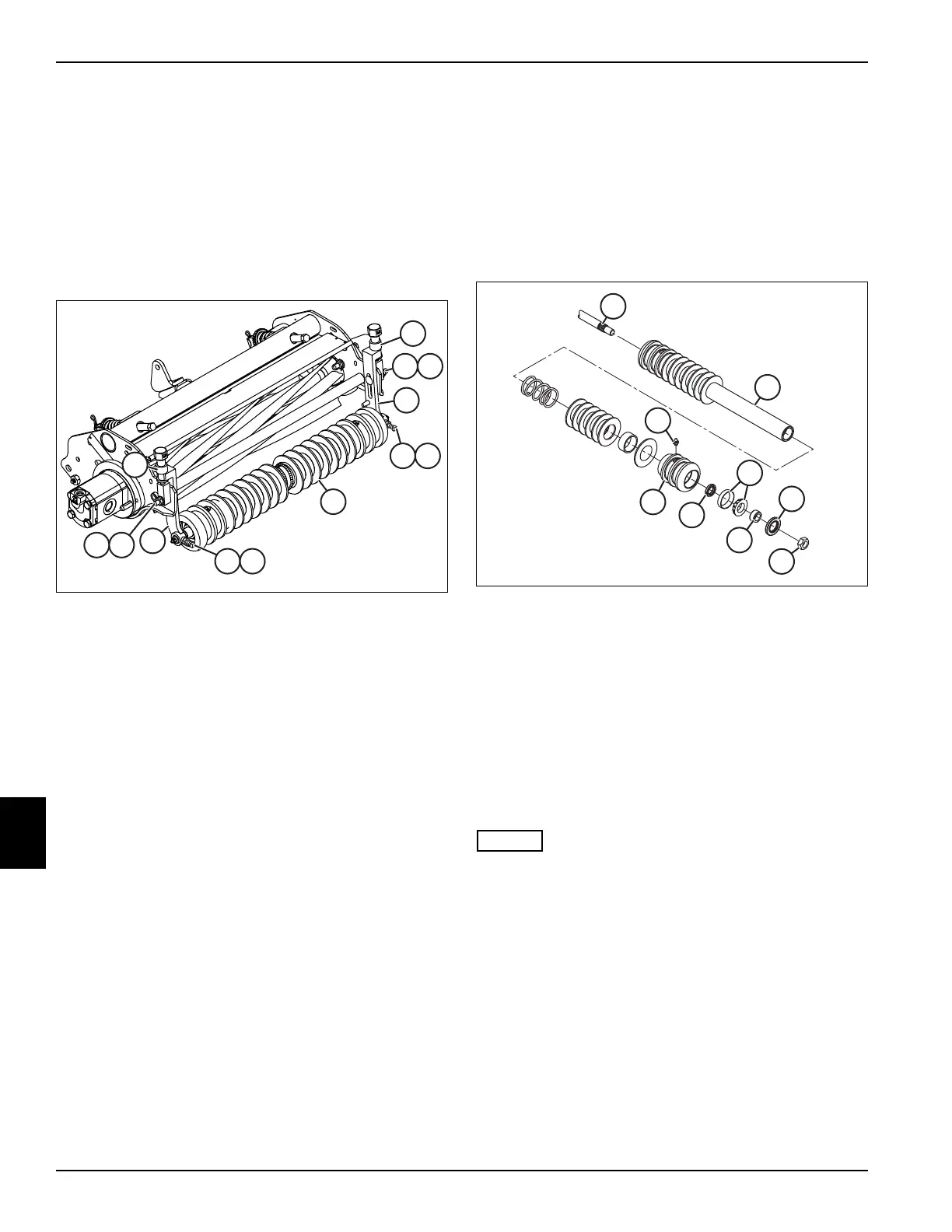
See Figure 8-32.
1. Park the mower safely. (See “Park Mower Safely” on
page 1-6.)
2. Raise cutting unit assembly with a suitable lifting
device and support the cutting unit frame to remove
weight from roller.
Figure 8-32
3. Remove nuts (3) and carriage bolts (4).
4. Remove adjuster knobs (1).
5. Remove adjuster brackets (2) and front roller (7) from
cutting unit.
6. Loosen jam nuts (5) and square head bolts (6) on
each side of front roller (7).
7. Remove front roller (7) from adjuster brackets (2).
Installation Notes
• Install front roller by reversing the order of removal.
• Center the roller between the adjuster brackets
before tightening jam nuts and square head bolts.
• Align roller shaft flat with square head bolts before
tightening bolt on flat on each end of shaft.
• Check height-of-cut adjustment. (See “Height-of-Cut
(HOC) Adjustment” on page 8-19.)
Front Roller Bearings
Removal
See Figure 8-33.
1. Park the mower safely. (See “Park Mower Safely” on
page 1-6.)
2. Remove front roller. (See “Front Roller” on
page 8-36.)
Figure 8-33
3. Remove lock nut (6) from each end of roller shaft (1).
4. Support one end of roller tube (2), and use a suitable
hammer to drive outer seal (5) and wear sleeve (7)
out of bearing housing (9) by tapping opposite end of
shaft (1).
5. Using a suitable puller, remove inner seal (8) and
bearing (4). Discard seals.
6. Repeat steps 4 and 5 for other end of roller.
Installation
• Clean and inspect bearings for wear or damage.
Replace if necessary.
• Pack bearings (4) with grease that meets or exceeds
NLGI Grade 2 LB specifications prior to installation.
• Apply grease that meets or exceeds NLGI Grade 2
LB specifications to the lips of seals (5 and 8) prior to
installation.
1. Using a suitable press, install new inner seals (8)
with single lip facing toward center of roller.
2. Press one bearing (4) onto end of roller shaft (1) and
install wear sleeve (7).
3. Carefully install roller shaft into roller tube without
damaging inner seals.
1
1
2
2
3 4
5 6
3 4
5 6
7

 Loading...

